A dc servo motor provides precise motion control, enabling accurate positioning and speed regulation in various applications. It consists of a rotary or linear actuator, which allows for such precise control of angular or linear position, velocity, and acceleration. It’s used in several sectors, including:
- Robotics
- Industrial automation
- Angular load positioning
- Avionics
- Automobiles
A few examples include:
- Robotic arms: most are pick-and-place robots composed of a minimum of two to six (or more) servo motors.
- Airplane and ship: servo motors are used in accurate angular positioning of rudder, elevator, aileron, and flaps in airplanes. They’re also used in rudder positioning in ships.
- Automobiles: servo motors are used in electronic power steering and cruise control systems of automobiles
One way to control servo-motor angle is by using a joystick, whereby the movement of a joystick (left-right-up-down) varies the angle of the servo motor. Typically, a single joystick movement controls the angles of multiple servo motors, which are attached to a rudder, elevator, aileron, etc., depending on the application.
In this project, we’ll program a wireless joystick to control two servo motors. The joystick will control a range of more than 1 km so that it can be used remotely.
The project consists of a joystick-based RF remote control built using a small, 8-pin microcontroller (ATtiny85) and a long-range RF trans-receiver module (HC12). The receiver side is built using Arduino NANO as the servo motor controller and the HC12 RF trans-receiver module.
System block-diagram
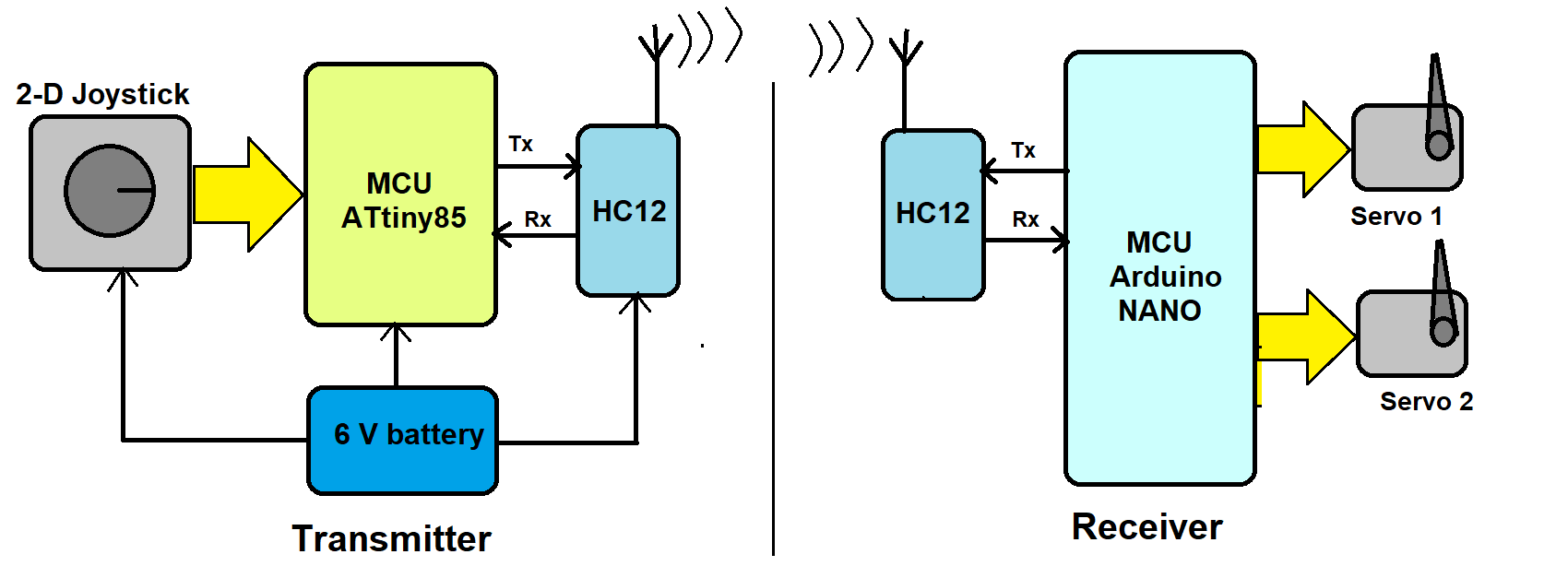
Figure 1. A system block diagram of joystick-controlled servo motors using ATtiny85, Arduino NANO and the HC12 sensor.
The system consists of two main parts:
1. Transmitter – a long-range RF remote control with a joystick
2. Receiver – a servo controller that controls the angles of two servo motors
Here’s a breakdown of the components:
- Transmitter: built using a joystick, the ATtiny85 microcontroller, the HC12 RF trans-receiver module, and a 6-V battery.
- Joystick: a two-axis resistive joystick that generates two analog outputs of 0 – 5 V (Vx and Vy) for its movement on the ‘X’ and ‘Y’ axes. These two outputs are given as input to ATtiny85.
- ATtiny85: a transmitter MCU. It receives analog inputs from the joystick, reading its ‘X’ and ‘Y’ directions and sending code based on these movements to the HC12 module.
- HC12: a 434 MHz RF serial trans-receiver module that receives specific code from the ATtiny85 serially and then transmits it.
- Battery: a Li-ion 6 V that’s used to provide power to all of the blocks.
- Receiver: built using Arduino NANO board, two dc servo motors, and the HC12 RF trans-receiver module.
- HC12: receives code transmitted by the HC12 module and sends it to Arduino NANO ATMega328 serially.
- Arduino NANO board: receives code serially from the HC12 and controls the angle of two servo motors as per the code. It generates two PWM signals to control the servo motor angle, rotating it clockwise and anti-clockwise.
Transmitter circuit diagram

Figure 2. A circuit diagram of the transmitter and ATtiny85 connected to the joystick and the HC12 module — all powered by a 6-V battery.
This transmitter circuit uses only five components: a joystick, ATtiny85, the HC12, an LED, and a battery.
The two-axis joystick has four connections: (1) Vcc, (2) Gnd, (3) Vx, (4) Vy.
- The Vcc and Gnd pins are connected with the battery’s +Ve and -Ve terminals for biasing.
- The Vx and Vy pins are connected to ATtiny85’s pins 2 and 3, the chip’s analog inputs.
The HC12 module has four connections: (1) Vcc, (2) Gnd, (3) Tx, (4) Rx.
- The Vcc and Gnd pins are connected with the battery’s +Ve and -Ve terminals for biasing
- The Tx and Rx pins are connected to ATtiny85’s digital I/O pins D1 (pin 6) and D2 (pin 7), which will work as the chip’s serial Rx and Tx pins.
The LED connects with ATtiny85’s digital I/O pin 5.
Receiver circuit diagram
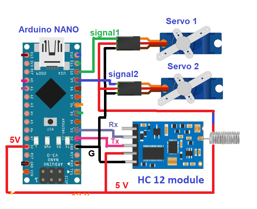
Figure 3. The circuit diagram of the receiver, with Arduino NANO connected to two servo motors and the HC12 module.
The receiver circuit uses two components — Arduino NANO and the HC12 module — along with two servo motors.
The HC12 module has four connections: (1) Vcc, (2) Gnd, (3) Tx, (4) Rx.
- The Vcc and Gnd pins are connected with the motor driver’s 5-V output and Gnd pins.
- The Tx and Rx pins are connected to Arduino’s digital I/O pins D2 and D3, which will work as serial Rx and Tx.
Both servo motors have three connections: (1) Vcc, (2) Gnd, (3) Signal.
- The Vcc pin is connected to Arduino’s 5-V output, and the Gnd pin is connected to the circuit ground.
- The signal input of servo motor 1 is the PWM output of Arduino’s D11.
- The signal input of servo motor 2 is the PWM output of Arduino’s D10.
How it works
Understanding the transmitter
The joystick
The joystick is a two-axis joystick, which means it has two potentiometers inside. Both potentiometers are connected to 5 V and the ground. As the joystick is moved from left to right, one potentiometer’s resistance varies, generating a variable output of 0 – 5V as Vx.
Similarly, as the joystick is moved up and down, the other potentiometer’s resistance varies, generating a variable output of 0 – 5V as Vy.
These Vx and Vy outputs are given as analog input to the ATtiny85 microcontroller.
The ATtiny85 microcontroller
ATtiny85 receives two analog inputs, Vx and Vy, from the joystick and converts them into an equivalent digital value using its built-in 10-bit ADC.
The analog voltage of 0 – 5V is converted into a digital value between 0 – 1023. The Vx analog voltage of 0-5 V is converted into the digital value ‘X,’ as 0 – 1023. The Vy analog voltage of 0-5 V is converted into the digital value ‘Y,’ as 0 – 1023.
If this digital value is above or below a certain threshold value, then ATtiny85 will send a specific code (a command) to the HC12 to be transmitted.
Refer to the below table for the codes.

This code is given serially to the HC12 module.
The HC12 module
The HC12 module receives the command serially from ATtiny85 and transmits it using a 434 MHz carrier.
The LED
The LED blinks each time ATtiny85 transmits code using the HC12.
Understanding the receiver
The HC12 module
The HC12 module receives the transmitted code and gives it serially to Arduino.
Arduino
Arduino receives code from the HC12 module and controls the angles of the two servo motors, per the following table.

Arduino generates two PWM signals to control the angles of both servo motors.
- When it receives the code ‘U,’ it increases the pulse width of pin D11, which increases the angle of servo motor 1.
- When it receives the code ‘D,’ it decreases the pulse width of pin D11, reducing the angle of servo motor 1.
- When it receives the code ‘R,’ it increases the pulse width on pin D10, which increases the angle of servo motor 2.
- When it receives the code ‘L,’ it decreases the pulse width on pin D10, reducing the angle of servo motor 2.
Software program
For the transmitter, the ATtiny85 program is prepared and compiled using Arduino IDE’s software. The program is written in Arduino C/C++ language. It reads the two analog inputs using Arduino’s analogRead() function from ATtiny85’s analog input pins A1 and A2. It communicates with the HC12 module serially using Arduino’s SoftwareSerial.h library through the digital I/O pins D1 and D2.
For the receiver, the Arduino program uses two libraries: SoftwareSerial.h and Servo.h.
The SoftwareSerial.h library communicates serially with the HC12 module through the digital pins D2 and D3. The Servo.h library controls the servo motor angle.
Servo.h is a built-in library for controlling the servo motor’s operation.
Here are the programs…
The transmitter program
The receiver program
Video
You may also like:


Filed Under: Electronic Projects, Video
Questions related to this article?
👉Ask and discuss on Electro-Tech-Online.com and EDAboard.com forums.
Tell Us What You Think!!
You must be logged in to post a comment.