ESP32-CAM is a compact camera module that combines the popular Wi-Fi development board ESP32 with the OV2640 camera sensor. The camera is part of the ESP32 series of Wi-Fi and Bluetooth-enabled system-on-chip (SoC) devices developed by Espressif Systems.
ESP32 is a dual-core 32-bit microcontroller with built-in Bluetooth and Wi-Fi capabilities — based on the Espressif IoT Development Framework (ESP-IDF). The combined OV2640 camera module offers a resolution of two megapixels, offering an affordable device for capturing images and video in an embedded application or Internet-of-Things (IoT) device.
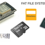
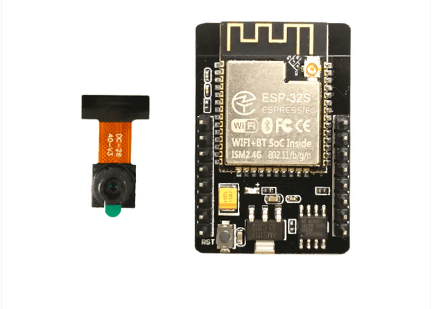 ESP32-CAM features a MicroSD card slot, which can be used for image and video storage. It also offers enough general-purpose input-output (GPIO) pins on the module to interface sensors and other peripherals directly.
The module can be easily programmed using Arduino IDE with the appropriate ESP32 board support package or the ESP-IDF for more advanced development. Programming is backed by large, active, open-source community support with several online libraries and examples.
However, despite its advantages, ESP32-CAM also has some drawbacks. In this article, we’ll review some common problems of working with this camera module and offer potential solutions.
Why choose the ESP32-CAM?
ESP32 camera offers several advantages for adding image or video-streaming functionalities to embedded applications. The camera module is compact, with built-in Wi-Fi and Bluetooth. It easily integrates with any IoT network and can operate in sleep mode for extended battery life for portable projects.
This low-cost module has a MicroSD card slot with internal connections to its GPIO for local storage of images and videos. It offers sufficient GPIO to interface additional sensors or peripherals with the module directly. It can also be programmed from Arduino IDE and has a large, open-source community, making it ideal for beginner or intermediate applications.
Limitations of the module
ESP32-CAM is attractive because it’s easy to use and affordable. However, it’s not ideal for computationally intensive tasks like running complex machine learning algorithms. The RAM available on the module is insufficient for high-resolution image-processing tasks. The camera resolution of the onboard OV2640 sensor is only two megapixels.
One major drawback of the ESP32-CAM is it lacks a USB port on most breakout boards, so it’s necessary to use an external FTDI programmer or an Arduino board to flash code into the module. The module also lacks built-in security measures when connecting with a network, which must be added to the embedded firmware if required.
Additionally, ESP32-CAM breakout boards get hot, especially with video streaming, potentially requiring heatsinks. Although there’s good community support for ESP32-CAM, the documentation is not ideal. It’s a steep learning curve to transition to ESP-IDF for building advanced projects using ESP32-CAM.
Applications
ESP32-CAM is a versatile module, thanks to its built-in Bluetooth, Wi-Fi, and MicroSD card capabilities. It’s useful in IoT projects like home automation, environmental monitoring, security, and surveillance. It’s also helpful for machine learning projects, such as object detection, face recognition, and other simple to intermediate image-based tasks. The module can even be used for wildlife monitoring and time-lapse photography.
Common problems with ESP32-CAM
- Power supply issues
- Failed to connect to ESP32
- Camera initialization failed
- Brownout detector
- Memory issues
- Board at COMX not available
- Psram error
- Wi-Fi connectivity
- No IP Address in Arduino IDE’s Serial Monitor
- Cannot open web server
- Image quality
- Image latency
- Overheating
- Security
- esp_camera_fb_get(): Failed to get the frame on time!
Let’s discuss these problems and their possible solutions.
Power supply issues
ESP32–CAM might not power up or may reboot frequently. This often occurs because of an inadequate or unstable power supply. Ensure a stable power supply with at least 500mA current capacity is powering the module. Also, use a quality USB cable and power supply, avoiding longer cables if possible.
The camera’s LED flash typically draws additional power, and powering it from the ESP32-CAM may cause voltage drops. Ideally, use an external battery pack, which is also good for portability. If powering the module through an FTDI programmer, use a 5V supply rather than a 3V3.
Failed to connect: Timed-out waiting for the packet header
This error occurs when uploading a sketch to the ESP32-CAM and indicates the module is not in flashing mode or not connected properly to the FTDI programmer.
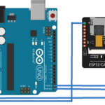
The circuit diagram to properly upload a sketch to ESP32-CAM through the FTDI programmer is as follows.

The circuit diagram for uploading the sketch to ESP32-CAM through Arduino is as follows.

If using an FTDI programmer, the programmer might have a jumper to select between 5 and 3.3V. If so, ensure the jumper is placed so that 5V is selected and ESP32-CAM’s GPIO0 is properly connected to the ground. Otherwise, the module will not go into the flashing mode.
Also, any FTDI programmers based on the CH340 model will not work with the ESP32 camera. Choose an ESP32-CAM-compatible FTDI programmer or flash code through Arduino. If using Arduino, make sure its reset pin is also connected to its ground.
After making proper circuit connections between ESP32-CAM and FTDI programmer/Arduino, ensure the proper settings are selected. For example, select ‘ESP32 Wrover Module’ or ‘AI-Thinker ESP32-CAM’ as per your ESP32 camera model in the Tools->Board. Also, choose the correct port for Arduino or the FTDI programmer and ensure it’s connected in the Tools->Port. When the upload button is clicked and ‘Connecting…’ is presented in the debug window, press the ESP32-CAM’s reset button. The sketch should begin to upload to the camera module.
Camera initialization failed
This problem indicates that the code’s pin assignment is incorrect or the camera OVX is not correctly linked to the ESP32 board. The issue can sometimes be resolved by repeatedly restarting the board or unplugging and plugging in the FTDI programmer.
However, there’s more than one potential reason for this error message. The camera has a tiny connector, so ensure it’s linked securely. Also, check that the correct camera model is selected in the code and that ESP32-CAM’s pin definition is correct within the sketch. In your projects, choose the appropriate camera module. Every camera module must be “commented,” but leave the right one “uncommented.”
It’s worth noting that the wiring between ESP32 and the OV camera on a lot of boards is considered “fake boards,” so there’s a chance that choosing the correct camera module might be insufficient. You might need to compare your board’s pinout with each GPIO declaration.
It’s also possible that the FTDI programmer might be faulty, or your computer’s USB port might not be supplying enough power to the camera module. Consider using another FTDI programmer or USB port.
This error also occurs when the camera sensor is not correctly connected to the module. The camera ribbon could be broken, or the OV2640 sensor might be faulty.
Brownout detector
After uploading the sketch to ESP32-CAM, disconnect the GPIO0 from the ground on the camera module. After the sketch uploads, open Arduino’s Serial Monitor and press the reset button on the module.
If you receive the error message, “Brownout detector was triggered” repeatedly in the serial console, the typical reason is because:
- The USB cable is too long or of low quality
- The computer’s USB port is malfunctioning
- The USB port is not supplying sufficient power
- The board is faulty
Try using a different USB cable or a different USB port. For instance, consider using a USB hub with an external power supply. Or, try using a 5V supply instead of 3.3V for the ESP32-CAM. If none of these solutions work, disable the Brownout detection by adding the following lines of code in your sketch.
#include “soc/soc.h”
#include “soc/rtc_cntl_reg.h”
void setup() {
WRITE_PERI_REG(RTC_CNTL_BROWN_OUT_REG, 0);
}
Memory issues
The ESP32-CAM has limited RAM, so memory-related problems might occur when working with large images or complex programs. Efficient memory management is crucial to prevent crashes.
You might encounter an error ‘Sketch Too Big’ right while uploading the sketch. Be sure to select the correct partition scheme. Navigate to Tools-> Partition Scheme and select ‘Huge APP (3MB No OTA).’
Board at COMX not available
If the error “Board at COMX is not available” occurs, you likely haven’t selected the correct Arduino COM port. Navigate to Tools-> Port and the COM port that ESP32 is connected to. A problem with the USB cable or the computer’s USB port might also generate this error.
PSRAM error: GPIO ISR service is not installed
This error will occur if your ESP32-CAM board doesn’t have PSRAM. Image-based tasks like face recognition and object detection are impossible on such boards.
Ideally, choose an ESP32-CAM model that has PSRAM. But if you have a board without PSRAM, a workaround is lowering the image resolution in the sketch.
Add the following lines of code to the sketch.
if(psramFound()){
config.frame_size = FRAMESIZE_UXGA;
config.jpeg_quality = 10;
config.fb_count = 2;
} else {
config.frame_size = FRAMESIZE_SVGA;
config.jpeg_quality = 12;
config.fb_count = 1;
}
Wi-Fi connectivity
Wi-Fi network issues could occur due to incorrect credentials, signal strength, or interference. Double-check your Wi-Fi signal strength and update firmware if necessary.
Also, experiment with different antenna positions for better reception. The ESP32-CAM can be configured to use an external or built-in antenna, which can be used if a Wi-Fi signal is weak.
Otherwise, verify that the jumper 0K resistor next to the antenna connector is positioned correctly. Three small white squares are arranged as a “<,” with the middle position typically the most popular. The resistor must be in the top position to use the PCB antenna and in the bottom position to use the antenna connector. To activate the onboard antenna, unsolder the resistor that connects to it and solder the two connections together.
No IP address in Arduino IDE Serial Monitor
If there’s a reliable Wi-Fi signal, but dots (such as ‘………’) still occur in the serial console, then ESP32-CAM is not properly connected to the Wi-Fi network. There could be several reasons for this.
Double-check the following, ensuring:
- You have entered the correct network Wi-Fi credentials in the sketch.
- ESP32-CAM’s baud rate is 115200 bps.
- ESP32-CAM’s TX and RX pins are securely connected to Arduino’s or FTDI programmer’s TX and RX pins.
Connecting ESP32-CAM’s TX with Arduino’s or the FTDI programmer’s RX and/or ESP32-CAM’s RX with Arduino’s or the FTDI programmer’s ESP32-CAM’s is a common error. “TX” must be connected to “TX,” and “RX” must be connected to “RX” for proper serial communication. Sometimes, pressing the reset button on the camera module repeatedly also solves the problem.
Cannot open the web server
When the ESP32-CAM reports the IP address in Arduino’s IDE Serial Monitor, but a blank screen appears when opening the web server in a browser, you might be accessing the web server through multiple tabs.
ESP32-CAM can only handle HTTP requests from a single client, so try accessing the web server from a single tab on the browser.
Poor image quality
If you’re connected to a web server but receiving blurry or distorted images, try adjusting the camera settings — including the resolution, frame rate, and white balance. Ensure proper focus by adjusting the lens. Also, try cleaning the camera lens for clear visuals.
Image latency
There might be latency in seeing images or video streams on the web server with some modules. This can be solved by using a standalone 5V power supply for the camera module. In some cases, using an external antenna is useful.
If there are still latency issues, try reducing the frame size by adding the following line of code in the sketch.
config.frame_size = FRAMESIZE_SVGA
Or, alternatively, try this:
config.frame_size = FRAMESIZE_VGA
Overheating
ESP32-CAM can overheat, especially during video streaming. Try reducing the video resolution and frame rate. Add a heatsink to dissipate heat, particularly for demanding tasks, and ensure proper ventilation in the project enclosure.
Security
There are potential security vulnerabilities with the ESP32-CAM when connected to the Internet. These security lapses can be avoided by using strong passwords and encryption. You can also implement authentication and authorization mechanisms if required. Always keep the firmware updated for security patches.
esp_camera_fb_get(): Failed to get the frame on time!
This error typically occurs with the M5 models and those without PSRAM. For the M5 model, the issue can be resolved by adding pin assignments in the sketch.
Consider adding this line of code in the main sketch.
#define CAMERA_MODEL_M5STACK_NO_PSRAM
Then, in the camera_pins.h tab, add the following lines of code:
#elif defined(CAMERA_MODEL_M5STACK_NO_PSRAM)
#define PWDN_GPIO_NUM -1
#define RESET_GPIO_NUM 15
#define XCLK_GPIO_NUM 27
#define SIOD_GPIO_NUM 25
#define SIOC_GPIO_NUM 23
#define Y9_GPIO_NUM 19
#define Y8_GPIO_NUM 36
#define Y7_GPIO_NUM 18
#define Y6_GPIO_NUM 39
#define Y5_GPIO_NUM 5
#define Y4_GPIO_NUM 34
#define Y3_GPIO_NUM 35
#define Y2_GPIO_NUM 17
#define VSYNC_GPIO_NUM 22
#define HREF_GPIO_NUM 26
#define PCLK_GPIO_NUM 21
This should solve the problem.
Conclusion
For simple image-processing tasks in IoT devices and embedded applications, ESP32-CAM is a good choice. It’s efficient, affordable, and easy to integrate. However, quite a few problems can occur with this module. Fortunately, most of them can be resolved by following simple suggestions.
You may also like:


Filed Under: Tech Articles
Questions related to this article?
👉Ask and discuss on EDAboard.com and Electro-Tech-Online.com forums.
Tell Us What You Think!!
You must be logged in to post a comment.