Engineers Garage

  • Electronic Projects & Tutorials
    • Electronic Projects
      • Arduino Projects
      • AVR
      • Raspberry pi
      • ESP8266
      • BeagleBone
      • 8051 Microcontroller
      • ARM
      • PIC Microcontroller
      • STM32
    • Tutorials
      • Audio Electronics
      • Battery Management
      • Brainwave
      • Electric Vehicles
      • EMI/EMC/RFI
      • Hardware Filters
      • IoT tutorials
      • Power Tutorials
      • Python
      • Sensors
      • USB
      • VHDL
    • Circuit Design
    • Project Videos
    • Components
  • Articles
    • Tech Articles
    • Insight
    • Invention Stories
    • How to
    • What Is
  • News
    • Electronic Product News
    • Business News
    • Company/Start-up News
    • DIY Reviews
    • Guest Post
  • Forums
    • EDABoard.com
    • Electro-Tech-Online
    • EG Forum Archive
  • DigiKey Store
    • Cables, Wires
    • Connectors, Interconnect
    • Discrete
    • Electromechanical
    • Embedded Computers
    • Enclosures, Hardware, Office
    • Integrated Circuits (ICs)
    • Isolators
    • LED/Optoelectronics
    • Passive
    • Power, Circuit Protection
    • Programmers
    • RF, Wireless
    • Semiconductors
    • Sensors, Transducers
    • Test Products
    • Tools
  • Learn
    • eBooks/Tech Tips
    • Design Guides
    • Learning Center
    • Tech Toolboxes
    • Webinars & Digital Events
  • Resources
    • Digital Issues
    • EE Training Days
    • LEAP Awards
    • Podcasts
    • Webinars / Digital Events
    • White Papers
    • Engineering Diversity & Inclusion
    • DesignFast
  • Guest Post Guidelines
  • Advertise
  • Subscribe

Designing a servo motor angle controller using IC NE555

By Ashutosh Bhatt December 15, 2021

The article discusses designing a servo motor angle controller using the IC NE555. The servo motor used here for an experiment is an 11-gram micro servo motor with the following specifications.

  1. Rotational range                                    160o
  2. Operating voltage                                  8 – 6 V
  3. Operating speed                                    500 deg/sec @ 4.8 V or 600 deg/sec @ 6V
  4. Stall torque                                             8 KG/CM OR 2.4 KG/CM
  5. Pulse width                                             550 us (0o) to 2.2 ms (160o)
  6. Pulse repetition frequency (PRF)         50 Hz

The servo motor always has three terminals, one for +Ve voltage, another for –Ve voltage, and the third one for PWM input signal. Also, these three terminals are color-coded. In most motors, the red wire is for +Ve voltage input, the brown or orange wire is for –Ve voltage input and the yellow or green wire is for PWM signal input.

The motor is given supply through +Ve and –Ve wires by connecting +Ve wire with 5 to 6 V and –Ve wire with ground. PWM input is the actual signal that rotates the motor at the exact angle. As the width of the input pulse is varied from 500 us to 2200 us (2.2 ms), the motor rotates from 0o to 160o. Also, the pulse has to be applied at a rate of 50 Hz, that is, after every 20 ms. As a pulse width continuously increases from 500 us to 2200 us, the motor angle increases from 0o to 160o and vice versa.

But as we know, the IC NE555 is also widely used for generating PWM signals. So, to accurately control the servo motor angle and rotate it to an exact angle, it is required to apply a precise PWM signal, which is possible with a microcontroller. Here we illustrate how a simple servo motor angle controller can be built using the IC NE555.

The IC NE555 has to be configured in astable mode to generate continuous pulses, and also, its ON time must be significantly less compared to OFF time. See the figure given below to understand it better.

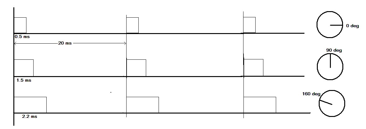
To generate such a waveform, we need the following astable configuration of the IC NE555.
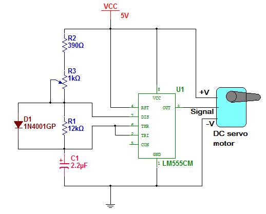
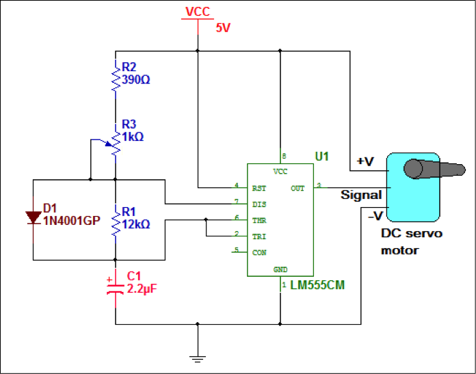
Circuit diagram
The figure shows that the IC NE555 is connected in astable mode with resistors R1, R2, and capacitor C1. There is an addition of a diode connected across R1 between terminals 7 and 6, bypassing R1 during the charging of C1. The chip’s output is connected to the PWM signal input of the servo motor. The circuit is given supply from 5 V. 

Circuit design
In this circuit value of R1 and C1 is fixed, but the value of R2 has to be variable to vary the width of the pulse. So to design the circuit to generate the required PWM wave, we have to find out the values of R1, R2, and C1. So let us start.

Ttotal = TON -TOFF
TOFF = Ttotal -TON
= 20 – 2.2
= 17.8
≈ 18 ms
Now, the equation for Toff is
TOFF = 0.69×R1×C1
Let us assume C1 as 2.2 uF. Substituting values
18×10-3 = 0.69×R1×2.2×10-6
This will give us R1 as
R1 = 11.85 KΩ
So, take R1 as 12 KΩ. This gives us two values for circuit design
R1 = 12 KΩ and C1 = 2.2 uF
Minimum ON time is 550 us. It is minimum when R2 is minimum. The ON time equation is same
TON = 0.69×R2min×C1
We know values of TON and C1 so,
550×10-6 = 0.69×R2min×2.2×10-6
This gives R2min as R2min = 362Ω
The nearest actual value of R2 is 390 Ω. So R2 can be 390 Ω.
Now, go for maximum ON time that is 2200 us. Obviously it will be when R2 is maximum.
So,TON = 0.69×R2max×C12200×10-6 = 0.69×R2max×2.2×10-6
This gives R2max as
R2max = 1450Ω = 1.4 K ≈ 1K + 390 Ω

So if we choose R2 as one fixed resistance of 390 Ω and one pot of 1 K Ω then the circuit design may be perfect.

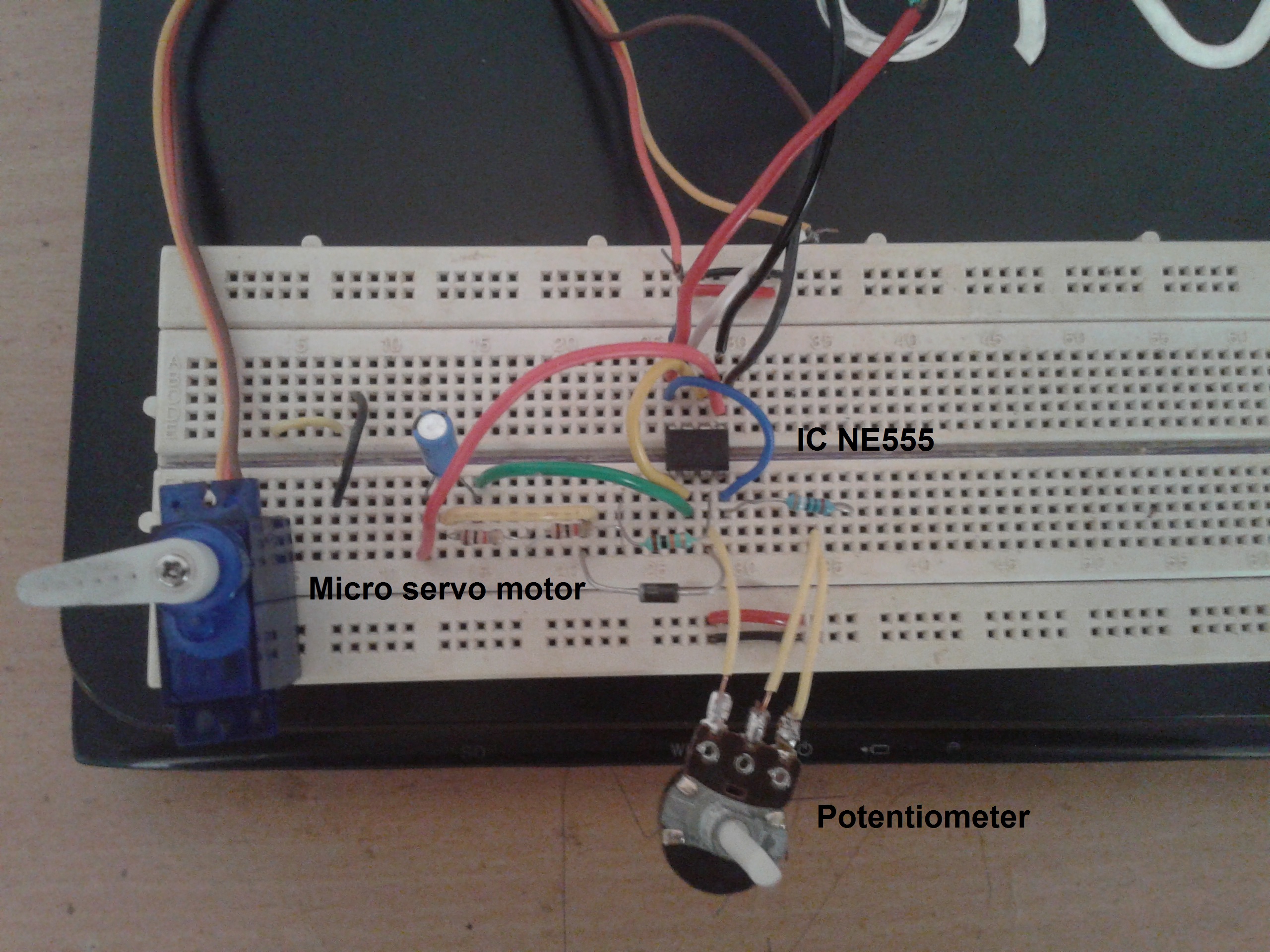
Here is the snap of the circuit built on the breadboard


Circuit operation
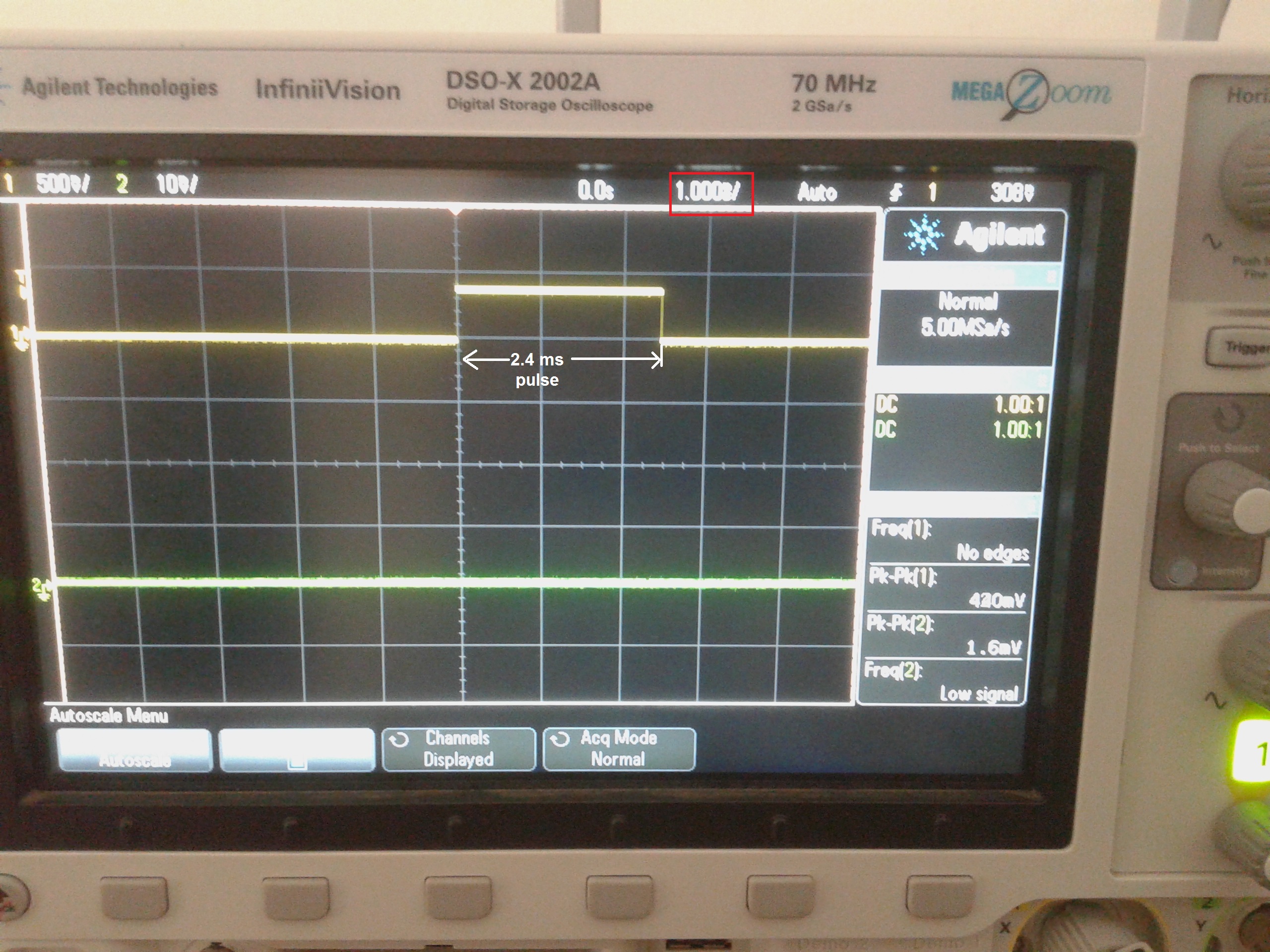
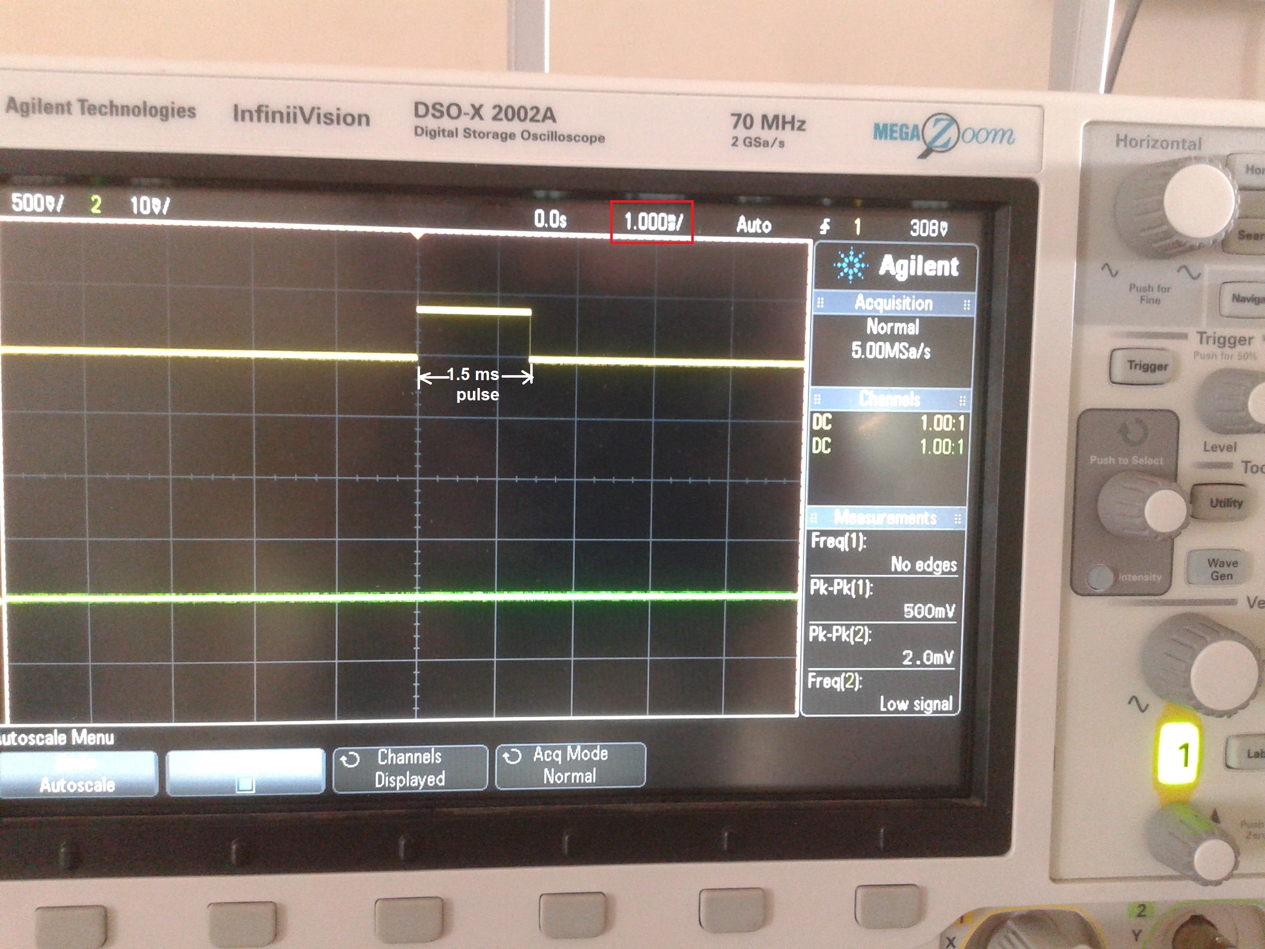
When the circuit is given a 5V supply, it generates a PWM wave at 50 Hz. When this wave is given to the servo motor, it will rotate at a specific angle. As the pulse width increases, the motor angle increases and vice versa. Here are some of the snaps of circuit output on the DSO.

youtube video link of project


You may also like:


  • What to expect from the IoT in 2023

  • What are LoRa gateways and what types are available?

  • How to select drone motors

  • What types of motors are used in electric vehicles?

  • How to select an electronic speed controller for your drone

  • What are the components of robotic arms and industrial robots?

Filed Under: Electronic Projects
Tagged With: IC NE555, servo motor
 

Next Article

← Previous Article
Next Article →

Questions related to this article?
👉Ask and discuss on Electro-Tech-Online.com and EDAboard.com forums.


Tell Us What You Think!! Cancel reply

You must be logged in to post a comment.

EE TECH TOOLBOX

“ee
Tech Toolbox: Internet of Things
Explore practical strategies for minimizing attack surfaces, managing memory efficiently, and securing firmware. Download now to ensure your IoT implementations remain secure, efficient, and future-ready.

EE Learning Center

EE Learning Center
“engineers
EXPAND YOUR KNOWLEDGE AND STAY CONNECTED
Get the latest info on technologies, tools and strategies for EE professionals.

HAVE A QUESTION?

Have a technical question about an article or other engineering questions? Check out our engineering forums EDABoard.com and Electro-Tech-Online.com where you can get those questions asked and answered by your peers!


RSS EDABOARD.com Discussions

  • Input impedance matching network
  • High Side current sensing
  • The comparison of different Tcl script checkers
  • Voltage mode pushpull is a nonsense SMPS?
  • Reducing "shoot-through" in offline Full Bridge SMPS?

RSS Electro-Tech-Online.com Discussions

  • Back to the old BASIC days
  • Parts required for a personal project
  • PIC KIT 3 not able to program dsPIC
  • Failure of polypropylene motor-run capacitors
  • Siemens large industrial PLC parts

Featured – RPi Python Programming (27 Part)

  • RPi Python Programming 21: The SIM900A AT commands
  • RPi Python Programming 22: Calls & SMS using a SIM900A GSM-GPRS modem
  • RPi Python Programming 23: Interfacing a NEO-6MV2 GPS module with Raspberry Pi
  • RPi Python Programming 24: I2C explained
  • RPi Python Programming 25 – Synchronous serial communication in Raspberry Pi using I2C protocol
  • RPi Python Programming 26 – Interfacing ADXL345 accelerometer sensor with Raspberry Pi

Recent Articles

  • What is AWS IoT Core and when should you use it?
  • AC-DC power supply extends voltage range to 800 V DC
  • Infineon’s inductive sensor integrates coil system driver, signal conditioning circuits and DSP
  • Arm Cortex-M23 MCU delivers 87.5 µA/MHz active mode
  • STMicroelectronics releases automotive amplifiers with in-play open-load detection

EE ENGINEERING TRAINING DAYS

engineering

Submit a Guest Post

submit a guest post
Engineers Garage
  • Analog IC TIps
  • Connector Tips
  • Battery Power Tips
  • DesignFast
  • EDABoard Forums
  • EE World Online
  • Electro-Tech-Online Forums
  • EV Engineering
  • Microcontroller Tips
  • Power Electronic Tips
  • Sensor Tips
  • Test and Measurement Tips
  • 5G Technology World
  • Subscribe to our newsletter
  • About Us
  • Contact Us
  • Advertise

Copyright © 2025 WTWH Media LLC. All Rights Reserved. The material on this site may not be reproduced, distributed, transmitted, cached or otherwise used, except with the prior written permission of WTWH Media
Privacy Policy

Search Engineers Garage

  • Electronic Projects & Tutorials
    • Electronic Projects
      • Arduino Projects
      • AVR
      • Raspberry pi
      • ESP8266
      • BeagleBone
      • 8051 Microcontroller
      • ARM
      • PIC Microcontroller
      • STM32
    • Tutorials
      • Audio Electronics
      • Battery Management
      • Brainwave
      • Electric Vehicles
      • EMI/EMC/RFI
      • Hardware Filters
      • IoT tutorials
      • Power Tutorials
      • Python
      • Sensors
      • USB
      • VHDL
    • Circuit Design
    • Project Videos
    • Components
  • Articles
    • Tech Articles
    • Insight
    • Invention Stories
    • How to
    • What Is
  • News
    • Electronic Product News
    • Business News
    • Company/Start-up News
    • DIY Reviews
    • Guest Post
  • Forums
    • EDABoard.com
    • Electro-Tech-Online
    • EG Forum Archive
  • DigiKey Store
    • Cables, Wires
    • Connectors, Interconnect
    • Discrete
    • Electromechanical
    • Embedded Computers
    • Enclosures, Hardware, Office
    • Integrated Circuits (ICs)
    • Isolators
    • LED/Optoelectronics
    • Passive
    • Power, Circuit Protection
    • Programmers
    • RF, Wireless
    • Semiconductors
    • Sensors, Transducers
    • Test Products
    • Tools
  • Learn
    • eBooks/Tech Tips
    • Design Guides
    • Learning Center
    • Tech Toolboxes
    • Webinars & Digital Events
  • Resources
    • Digital Issues
    • EE Training Days
    • LEAP Awards
    • Podcasts
    • Webinars / Digital Events
    • White Papers
    • Engineering Diversity & Inclusion
    • DesignFast
  • Guest Post Guidelines
  • Advertise
  • Subscribe