Engineers Garage

  • Electronic Projects & Tutorials
    • Electronic Projects
      • Arduino Projects
      • AVR
      • Raspberry pi
      • ESP8266
      • BeagleBone
      • 8051 Microcontroller
      • ARM
      • PIC Microcontroller
      • STM32
    • Tutorials
      • Audio Electronics
      • Battery Management
      • Brainwave
      • Electric Vehicles
      • EMI/EMC/RFI
      • Hardware Filters
      • IoT tutorials
      • Power Tutorials
      • Python
      • Sensors
      • USB
      • VHDL
    • Circuit Design
    • Project Videos
    • Components
  • Articles
    • Tech Articles
    • Insight
    • Invention Stories
    • How to
    • What Is
  • News
    • Electronic Product News
    • Business News
    • Company/Start-up News
    • DIY Reviews
    • Guest Post
  • Forums
    • EDABoard.com
    • Electro-Tech-Online
    • EG Forum Archive
  • DigiKey Store
    • Cables, Wires
    • Connectors, Interconnect
    • Discrete
    • Electromechanical
    • Embedded Computers
    • Enclosures, Hardware, Office
    • Integrated Circuits (ICs)
    • Isolators
    • LED/Optoelectronics
    • Passive
    • Power, Circuit Protection
    • Programmers
    • RF, Wireless
    • Semiconductors
    • Sensors, Transducers
    • Test Products
    • Tools
  • Learn
    • eBooks/Tech Tips
    • Design Guides
    • Learning Center
    • Tech Toolboxes
    • Webinars & Digital Events
  • Resources
    • Digital Issues
    • EE Training Days
    • LEAP Awards
    • Podcasts
    • Webinars / Digital Events
    • White Papers
    • Engineering Diversity & Inclusion
    • DesignFast
  • Guest Post Guidelines
  • Advertise
  • Subscribe

How to create a constant current source using LM338

By Ayush Jain October 3, 2023

Voltage and current sources are two fundamental types of electrical sources used in electronic circuits. A voltage source, such as a battery, is commonly used in many devices. It’s a two-terminal device that maintains a constant voltage across its terminals, regardless of the current flowing through the source.

A current source is typically less discussed and more difficult and costly to design. It’s also a two-terminal device, but it maintains a constant current through its terminals, regardless of the voltage across the source. This means it’s used to ensure a steady current even if the load fluctuates.

In this experiment, we’ll design a constant current source application using a linear buck regulator.

Specifications

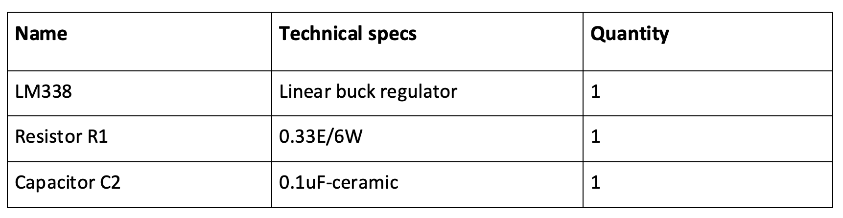
  • The LM338 linear buck regulator
  • Input voltage range – 1.2 to 32V
  • Maximum output current – 5A

Block diagram 

Block diagram of constant current source using a linear buck convertor.
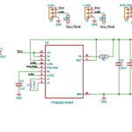
Circuit diagram

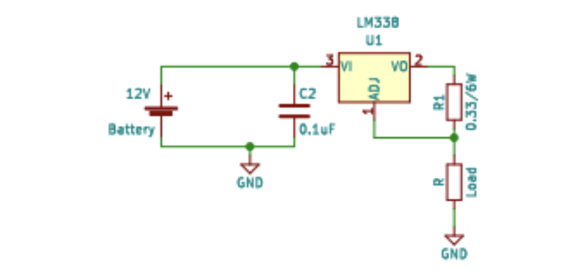
Circuit diagram of a constant current source using LM338.

Principle
When using any linear regulator as a current source, the circuit works on the principle of a feedback loop. 

The regulator consists of a feedback pin (the adjust pin) that feeds the output back to the regulator and maintains a fixed voltage at the feedback network. This network is a resistor, which determines the output current at the output. 

Circuit design
Here are the steps for the circuit design.

1. Input source – 24V DC
2. Linear buck converter – LM338 IC 

Features of the LM338 

  • Overload protection – in case of overloading, the device will reduce its output current until the overload is removed
  • Thermal regulation
  • Output short-circuit protection

3. Output current set – the output current is based on the feedback network, which is the resistor

The equation for calculating the feedback resistor…
By applying famous Ohm’s law, we get:
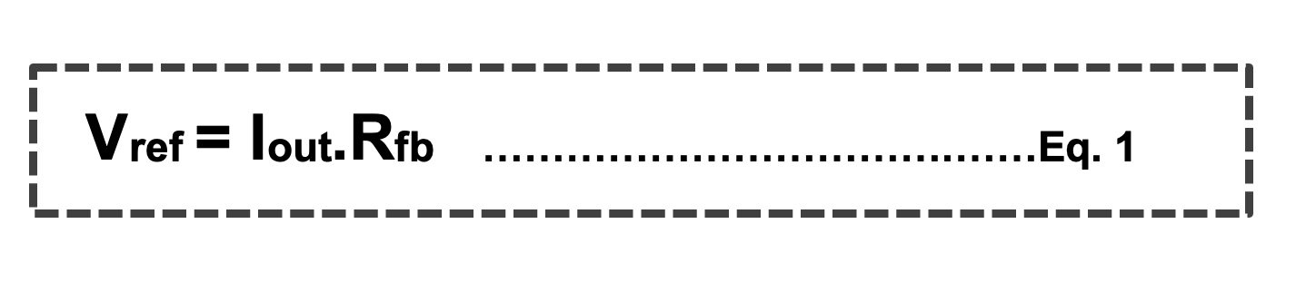
.  Vref = voltage reference of the regulator

LM338 regulator, Vref =1.25V

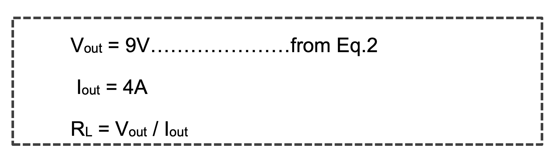
Desired constant output current, Iout  = 4A

Feedback resistor, Rfb  = Vref / Iout

Rfb = 1.25/5

Rfb = 0.33E

4. Feedback resistor power rating

The equation for calculating power rating of the resistor…

PR = I2*Rfb

PR = (4*4)*0.33

PR = 5.28W (minimum)

5. Filtering – the capacitor, which is at the input, grounds all of the ripples and spikes from the source. To reduce the total ESR, we can connect a ceramic capacitor along with an electrolyte.

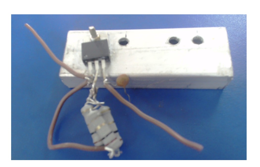
6. Cooling system – the heat sink must be mounted with the regulator because we’re drawing a large amount of current. This will produce a lot of heat at the IC surface and can ignite it. So, it’s important to use a cooling fan or a heat sink to reduce its temperature.

How the circuit works
In our constant current source, the feedback loop maintains a fixed output voltage across the feedback resistor. As per Ohm’s law, with a fixed value of voltage and a resistor, a constant amount of current will flow. 

This will generate a constant current at the output, irrespective of the load.

Output current regulation
All current sources provide a regulated current but only for a specific load range. 

It’s possible to calculate the load limit for the linear regulator by using the following equation… 
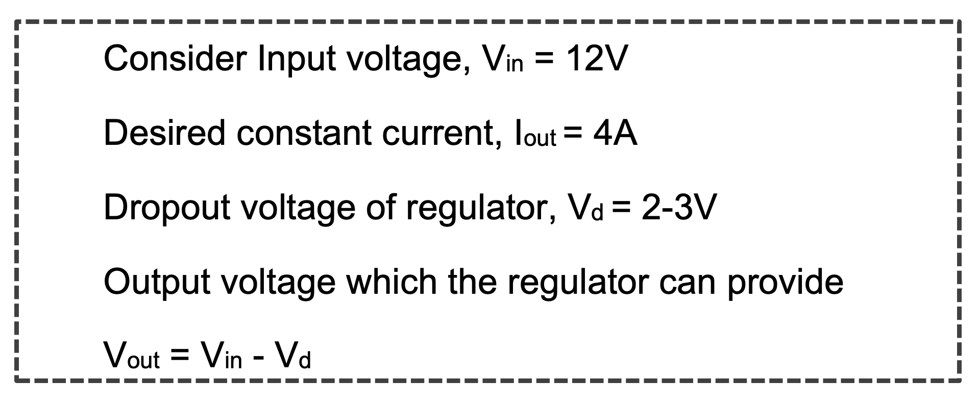
Vout = 12 – 3

Vout = 9V…………………………Eq.2
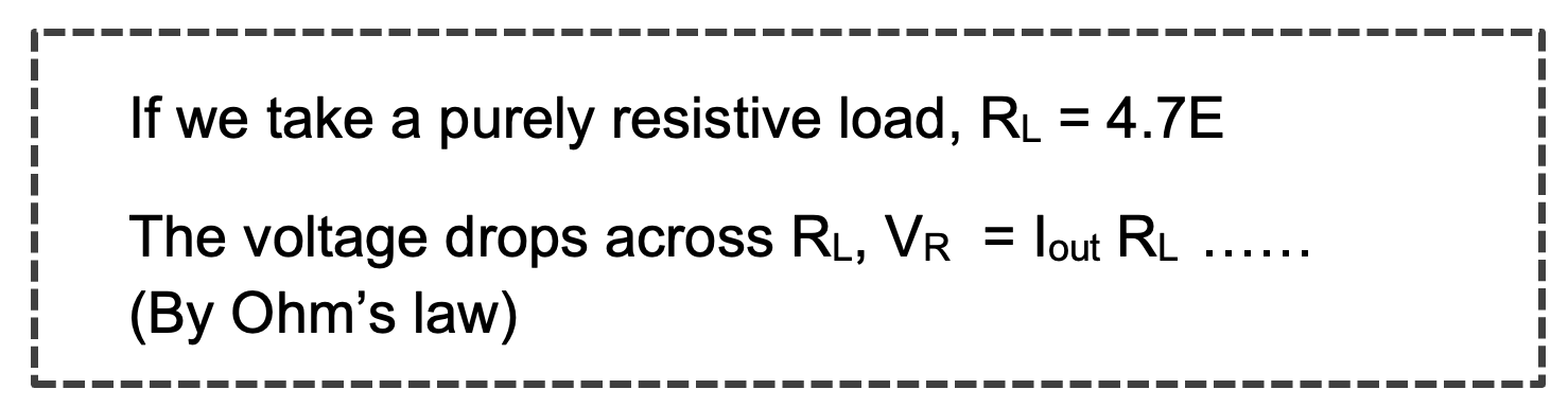
VR = 5*4.7

VR = 23.5V

The regulator is unable to provide 23.5V at the output. So, we must first calculate the output load limit using the equation below…

The maximum value of resistive load, RL = 2.25E


Testing results
Initially, we designed the current source for 5A since the IC is rated for 5A output current. However, the IC could not maintain a constant 5A output current and began dropping its value even with a heat sink and cooling fan. 

This might be because of the IC’s internal thermal regulation, which tries to maintain its temperature and drops the current if in a high-power dissipation state. 

So, instead, we tried the circuit using a 3.7A current, and it worked perfectly with the heat sink. 

Observation

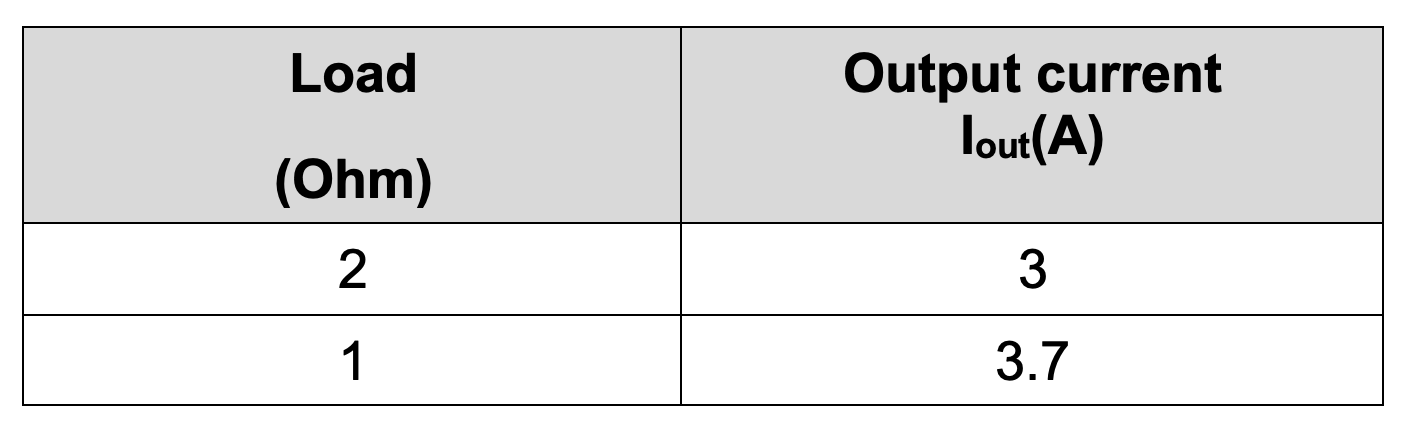
The output current begins stabilizing at a load of 1 Ohm. The difference in the output current is due to the resistor’s tolerance values.

Circuit limitations

  1. Input source – A high-voltage input source is needed to increase the maximum load limit
  2. Cost – A high power rating feedback resistor increases the cost
  3. Efficiency – There’s less efficiency because of high-power dissipation across the feedback resistor

Thermal management
For extra heat dissipation, heat is connected to the IC. It’s also possible to use a fan to disperse the hot air.

Applications

  1. Battery charging
  2. In transistor biasing
  3. Lighting systems
  4. Regulated supply

Precautions 

  1. Ensure the feedback resistor’s power rating is per the product requirements. 
  2. Always put a load under the limits of the current source. 
  3. A capacitor should be connected between the input pin and ground to regulate the DC input voltage. 
  4. The circuit’s capacitor must have a higher voltage rating than the input supply voltage. Otherwise, the capacitor will leak current due to the excess voltage at its plates and burst.
  5. Ensure all the capacitors are discharged before working on a DC power supply.
  6. Do not give a higher voltage at input than its operating input voltage range.
  7. Always connect a heat sink or a cooling fan for heat dissipation around the IC.

Video

https://www.engineersgarage.com/wp-content/uploads/2023/10/Video.mp4


You may also like:


  • How to use a buck-boost converter to regulate a Li-ion…

  • How to use a boost converter with a Li-ion battery…

  • How to design a constant current source using a linear…

  • A guide to bipolar junction transistors

  • What are the types of drones and how are they…

Filed Under: Tutorials
Tagged With: buckconverter, constantcurrent, current, currentsource, lm338, powermanagement, voltage
 

Next Article

← Previous Article
Next Article →

Questions related to this article?
👉Ask and discuss on Electro-Tech-Online.com and EDAboard.com forums.


Tell Us What You Think!! Cancel reply

You must be logged in to post a comment.

EE TECH TOOLBOX

“ee
Tech Toolbox: Internet of Things
Explore practical strategies for minimizing attack surfaces, managing memory efficiently, and securing firmware. Download now to ensure your IoT implementations remain secure, efficient, and future-ready.

EE Learning Center

EE Learning Center
“engineers
EXPAND YOUR KNOWLEDGE AND STAY CONNECTED
Get the latest info on technologies, tools and strategies for EE professionals.

HAVE A QUESTION?

Have a technical question about an article or other engineering questions? Check out our engineering forums EDABoard.com and Electro-Tech-Online.com where you can get those questions asked and answered by your peers!


RSS EDABOARD.com Discussions

  • Voltage mode pushpull is a nonsense SMPS?
  • Input impedance matching network
  • High Side current sensing
  • The comparison of different Tcl script checkers
  • Reducing "shoot-through" in offline Full Bridge SMPS?

RSS Electro-Tech-Online.com Discussions

  • Is AI making embedded software developers more productive?
  • Back to the old BASIC days
  • Parts required for a personal project
  • PIC KIT 3 not able to program dsPIC
  • Failure of polypropylene motor-run capacitors

Featured – RPi Python Programming (27 Part)

  • RPi Python Programming 21: The SIM900A AT commands
  • RPi Python Programming 22: Calls & SMS using a SIM900A GSM-GPRS modem
  • RPi Python Programming 23: Interfacing a NEO-6MV2 GPS module with Raspberry Pi
  • RPi Python Programming 24: I2C explained
  • RPi Python Programming 25 – Synchronous serial communication in Raspberry Pi using I2C protocol
  • RPi Python Programming 26 – Interfacing ADXL345 accelerometer sensor with Raspberry Pi

Recent Articles

  • What is AWS IoT Core and when should you use it?
  • AC-DC power supply extends voltage range to 800 V DC
  • Infineon’s inductive sensor integrates coil system driver, signal conditioning circuits and DSP
  • Arm Cortex-M23 MCU delivers 87.5 µA/MHz active mode
  • STMicroelectronics releases automotive amplifiers with in-play open-load detection

EE ENGINEERING TRAINING DAYS

engineering

Submit a Guest Post

submit a guest post
Engineers Garage
  • Analog IC TIps
  • Connector Tips
  • Battery Power Tips
  • DesignFast
  • EDABoard Forums
  • EE World Online
  • Electro-Tech-Online Forums
  • EV Engineering
  • Microcontroller Tips
  • Power Electronic Tips
  • Sensor Tips
  • Test and Measurement Tips
  • 5G Technology World
  • Subscribe to our newsletter
  • About Us
  • Contact Us
  • Advertise

Copyright © 2025 WTWH Media LLC. All Rights Reserved. The material on this site may not be reproduced, distributed, transmitted, cached or otherwise used, except with the prior written permission of WTWH Media
Privacy Policy

Search Engineers Garage

  • Electronic Projects & Tutorials
    • Electronic Projects
      • Arduino Projects
      • AVR
      • Raspberry pi
      • ESP8266
      • BeagleBone
      • 8051 Microcontroller
      • ARM
      • PIC Microcontroller
      • STM32
    • Tutorials
      • Audio Electronics
      • Battery Management
      • Brainwave
      • Electric Vehicles
      • EMI/EMC/RFI
      • Hardware Filters
      • IoT tutorials
      • Power Tutorials
      • Python
      • Sensors
      • USB
      • VHDL
    • Circuit Design
    • Project Videos
    • Components
  • Articles
    • Tech Articles
    • Insight
    • Invention Stories
    • How to
    • What Is
  • News
    • Electronic Product News
    • Business News
    • Company/Start-up News
    • DIY Reviews
    • Guest Post
  • Forums
    • EDABoard.com
    • Electro-Tech-Online
    • EG Forum Archive
  • DigiKey Store
    • Cables, Wires
    • Connectors, Interconnect
    • Discrete
    • Electromechanical
    • Embedded Computers
    • Enclosures, Hardware, Office
    • Integrated Circuits (ICs)
    • Isolators
    • LED/Optoelectronics
    • Passive
    • Power, Circuit Protection
    • Programmers
    • RF, Wireless
    • Semiconductors
    • Sensors, Transducers
    • Test Products
    • Tools
  • Learn
    • eBooks/Tech Tips
    • Design Guides
    • Learning Center
    • Tech Toolboxes
    • Webinars & Digital Events
  • Resources
    • Digital Issues
    • EE Training Days
    • LEAP Awards
    • Podcasts
    • Webinars / Digital Events
    • White Papers
    • Engineering Diversity & Inclusion
    • DesignFast
  • Guest Post Guidelines
  • Advertise
  • Subscribe