This article is in continuation to AVR interrupts. There are two types of interrupts external and internal in AVR microcontroller. The aforesaid article covers [[wysiwyg_imageupload::]]external interrupts. AVR microcontrollers have seventeen internal interrupts. These internal interrupts are generated by the internal peripherals of Microcontroller like Timer, ADC etc. The internal interrupts are used for efficient operation of the internal peripherals. This article explains the internal interrupts using the example of an ADC interrupt. Each internal peripheral system consists of one IE (interrupt Enable) bit which activates the internal interrupts of that peripheral. For example, in-built ADC of AVR consists of ADIE (ADC interrupt Enable) bit in ADCSRA register.In addition, the I-bit of SREG is also activated to activate interrupts. SREG is a status register of AVR microcontroller which contains information about the result of most recently executed arithmetic instructions.
RFID interfacing with AVR microcontroller (ATmega16) using interrupts- (Part 40/46)
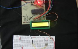
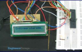
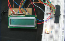
This article covers how to extract and display the twelve byte unique tag ID received by RFID module on LCD using interrupt method. Before proceeding to this [[wysiwyg_imageupload::]]article readers must have knowledge of serial interrupt and LCD. In the previous article of RFID, polling method was used where the microcontroller was continuously monitoring the RXC flag. Keeping the microcontroller busy in monitoring the flag is not a good programming technique, so instead of polling method a programmer should prefer using interrupts. Since the output data of the RFID module uses RS232 protocol and is serial in nature, serial interrupt is used to receive the twelve byte unique ID. Whenever an RFID tag comes in the proximity of the RFID reader module, the module transmits the twelve byte unique ID. Every time one byte of data is received, the controller is interrupted and the corresponding ISR gets executed, which stores the byte in a temporary variable and sends it to the LCD for display.
How to interface RFID with AVR microcontroller (ATmega16)- (Part 39/46)

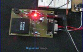
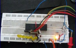
Knowingly or unknowingly the RFID technology is used by us in our day to day life. The most familiar example is seen in MNCs, schools and offices for daily [[wysiwyg_imageupload::]]attendance or automatic door opening system. The RFID contains two parts, namely, tag and receiver modem. When an RFID tag comes in the range of receiver, the tag gets activated and transmits its unique identification code to the receiver module.The output of the RFID receiver is the unique ID in either serial (RS232) or wiegand format. Most of the receivers are equipped with additional hardware to send the extracted code in the above format, which can then be used by digital signal processors. This article shows the interfacing of ATmega16 with RFID. The RFID module used here gives a 12 byte unique ID of a particular tag in serial RS232 logic level format. Hence a level converter MAX232 is used in between RFID receiver module and microcontroller. The connections of RFID module and ATmega16 are shown in the circuit diagram.
Serial communication with AVR microcontroller using interrupts- (Part 23/46)
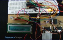
In our previous articles on serial data transmission using AVR microcontroller we have demonstrated serial communication using the polling method. In Polling, [[wysiwyg_imageupload::]]the microcontroller waits for the RXC flag (in the case of serial receiver) to go high and then moves to the next instruction. This is not a good programming technique to keep the microcontroller busy to monitor the RXC flag. Alternatively, serial interrupts can be used to transmit and receive data. This increases the efficiency of the code and keeps the processor free for other tasks. The article explains serial data reception using interrupts concepts. It is recommended that the readers should study the article on AVR Interrupts before proceeding. The UCSRB register has RXCIE (Reception Complete Interrupt Enable) bit, which is used to enable the serial reception interrupt. The I-bit of SREG register is must be set to enable global interrupt of ATmega16. The circuit diagram is same as used in previous article of USART.
How to interface AVR microcontroller with PC using USART (RS232 protocol)- (Part 13/46)

This article covers data transmission using 8 bit USART. The readers should have a basic understanding of serial communication and how to receive the serial [[wysiwyg_imageupload::]]data output. More details on these topics are available on Serial communication using AVR Microcontroller USART. The registers of USART system are already explained in previous article. Before transmitting the data, it must be stored in UDR register. The HyperTerminal software is used to show received data. A sequential process can be followed to transmit the data to COM port of computer. Continue reading to find out how interfacing and transmission through 8 bit USART can be done with the help of AVR microcontroller.
Serial communication (Data receive) using AVR Microcontroller (ATmega16) USART- (Part 12/46)
Communication between two entities is important for the information flow to take place. In general the information transport system can be parallel in which the [[wysiwyg_imageupload::]]complete byte of data is sent at a time, with each bit having a separate dedicated line or it can be serial where only one communication line is available which is shared by all the bits sequentially. The pros and cons of these two systems are equivalent and selection between the two depends on the application.Data can be exchanged using parallel or serial techniques. Setup for parallel data transfer is not cost effective but is a very fast method of communication. Serial communication is cost effective because it requires only a single line of connection but on the other hand is a slow process in comparison to parallel communication. This article explains serial communication of AVR microcontroller (ATmega16) with PC. The data is transmitted from the controller using RS232 standard and displayed on the PC using Hyper Terminal.
How to use inbuilt ADC of AVR microcontroller (ATmega16)- (Part 26/46)
Microcontroller understands only digital language. However, the inputs available from the environment to the microcontroller are mostly analog in nature, i.e., they [[wysiwyg_imageupload::]]vary continuously with time. In order to understand the inputs by the digital processor, a device called Analog to Digital Converter (ADC) is used. As the name suggests this peripheral gathers the analog information supplied from the environment and converts it to the controller understandable digital format, microcontroller then processes the information and provides the desired result at the output end. ATmega16 has an inbuilt 10 bit, 8-channel ADC system. Some of the basic features of Armega16 ADC are:· 8 Channels.· 10-bit Resolution.· Input voltage range of 0 to Vcc.· Selectable 2.56V of internal Reference voltage source.· AREF pin for External Reference voltage.· ADC Conversion Complete Interrupt.
Display custom characters on LCD using AVR Microcontroller (ATmega16)- (Part 9/46)

This is the most interesting article to play with LCD. After going through the article, you can create any character/symbol which cannot be created using the [[wysiwyg_imageupload::]]ASCII values for example smiley. You can even create small games. Conventionally 16X2 LCD is use to display text or numerical values. It is possible to display special characters, your own designed characters too on LCD by using its 5 x 8 matrix block. These special characters are stored in the CGRAM of LCD. This article shows how to create and display special character on LCD using ATmega16. For more details refer to the article how to create custom characters. This article assumes that the readers are aware of the concepts of interfacing LCD with AVR microcontroller (ATMEGA 16). For more information about interfacing LCD with AVR, refer How to display string on LCD using AVR. In order to create a custom character its configuration is first defined in the CGRAM of the LCD. A maximum of eight characters can be stored at a time in the 16 x 2 LCD.
How to display text on 16×2 LCD using AVR microcontroller (ATmega16)- (Part 8/46)
This article is in continuation to the article Single character LCD display using AVR. The aforesaid article shows how to display a single letter on LCD. Moving [[wysiwyg_imageupload::]]forward towards learning to work with LCD, this article explains how to display a string on LCD. Displaying string is occasionally used in many applications. The connection of the LCD with the AVR microcontroller (ATmega16) is shown in the circuit diagram. A string is nothing but a sequence of characters. The following steps explain how to display a string on the LCD. Keep on reading to find out How to code and interface in order to display text on 16×2 LCD using AVR microcontroller (ATmega16).
How to interface 16×2 LCD with AVR microcontroller (ATmega16)- (Part 7/46)
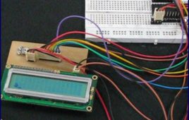
LCD is used to present textual information to the users. It is great fun to work with LCD. Also LCD makes your application more interactive. LCD comes in various [[wysiwyg_imageupload::]]configurations and the most popular one is 16×2 matrix display. This article shows the interfacing of ATmega16 with LCD by displaying a simple character on the LCD. For more information about LCD, refer the article LCD interfacing. In this project LCD is working in 8-bit mode i.e., the data transferred to the LCD must be in 8-bit data form. The PortA of ATmega16 is connected to data pins of LCD and is defined as LCD_DATA. PortB is defined as control pins (Rs, R/W and En). Conceptually, interfacing LCD with AVR microcontroller is similar to that of interfacing it with any other microcontroller. Continue reading to understand interfacing circuitry and coding concepts of the project.