Engineers Garage

  • Electronic Projects & Tutorials
    • Electronic Projects
      • Arduino Projects
      • AVR
      • Raspberry pi
      • ESP8266
      • BeagleBone
      • 8051 Microcontroller
      • ARM
      • PIC Microcontroller
      • STM32
    • Tutorials
      • Audio Electronics
      • Battery Management
      • Brainwave
      • Electric Vehicles
      • EMI/EMC/RFI
      • Hardware Filters
      • IoT tutorials
      • Power Tutorials
      • Python
      • Sensors
      • USB
      • VHDL
    • Circuit Design
    • Project Videos
    • Components
  • Articles
    • Tech Articles
    • Insight
    • Invention Stories
    • How to
    • What Is
  • News
    • Electronic Product News
    • Business News
    • Company/Start-up News
    • DIY Reviews
    • Guest Post
  • Forums
    • EDABoard.com
    • Electro-Tech-Online
    • EG Forum Archive
  • DigiKey Store
    • Cables, Wires
    • Connectors, Interconnect
    • Discrete
    • Electromechanical
    • Embedded Computers
    • Enclosures, Hardware, Office
    • Integrated Circuits (ICs)
    • Isolators
    • LED/Optoelectronics
    • Passive
    • Power, Circuit Protection
    • Programmers
    • RF, Wireless
    • Semiconductors
    • Sensors, Transducers
    • Test Products
    • Tools
  • Learn
    • eBooks/Tech Tips
    • Design Guides
    • Learning Center
    • Tech Toolboxes
    • Webinars & Digital Events
  • Resources
    • Digital Issues
    • EE Training Days
    • LEAP Awards
    • Podcasts
    • Webinars / Digital Events
    • White Papers
    • Engineering Diversity & Inclusion
    • DesignFast
  • Guest Post Guidelines
  • Advertise
  • Subscribe

Interfacing 3-Axis Accelerometer with 8051 Microcontroller

By Gurmeet Singh April 21, 2008


Requirements:

  1. AT89S52 (8051 microcontroller by ATMEL Corp.)
  2. ADXL-335 (or any 3- axis accelerometer )
  3. 16X2 alphanumeric LCD
  4. ADC0804 (8 bit analog to digital converter IC)
  5. 555 timer  (for providing clock frequency to ADC)
  6. 11.0592MH
  7. 7805 voltage regulator IC

Prototype of 8051 Microcontroller interfacing with ADXL335 Accelerometer Module

Fig. 1: Prototype of 8051 Microcontroller interfacing with ADXL335 Accelerometer Module

This project involves various stuffs like accelerometer module, 8 bit ADC, 555 timer IC, LCD display etc. So I’ll be discussing about all of them step by step.


ADXL 335 Accelerometer IC

First let’s talk about the Accelerometer IC; here I have used ADXL_335 which is a 3-axis accelerometer module. This module provides X, Y and Z axis data.

Image of ADXL335 Accelerometer Module

Fig. 2: Image of ADXL335 Accelerometer Module

It’s very easy to deal with such kind of modules as they just need the VCC and GND supply to get started, rest it is its job to provide us the analog data.

These modules work on simple concept like that of force acting on an object at inclined plane. It deals with the Mg(sin?) and Mg(cos?) part of the force and calculate the angle ? for further calculations. Now it also notices the change in force from which acceleration will be calculated.

These accelerometers do not respond to linear movements they respond to accelerated motions at very small scale.

Looking at the above picture you’ll notice that there is a ST pin. This pin deals with the value of ‘g’ (accelerations due to gravity) to be taken while calculating the result. Checkout its data sheet for more information. It will also work on a default value if you do not connect this pin anywhere.


ADC 0804

Now let’s talk about ADC_0804. I have used his IC to convert my analog data from ADXL_335 into a digital output. This was really necessary because microcontrollers only understand digital data.

Since this ADC is an 8 bit one, it will provide me 256 different digital values (0-255).


555 Timer IC

When coming on its working part, these ICs need a clock frequency to work on. Now I have used a 555 timer in a-stable mode but it can also be operated using its internal clock by just providing it an R-C circuit across it. This IC works properly on 640 KHz, so for 555 timer users do select the resistors and capacitor accordingly.

But how do we get to know about its functioning unless it is displayed somewhere. Therefore I have used a 16X2 LCD display to display the digital values on it. This will help us to see the values which correspond to different inclinations.


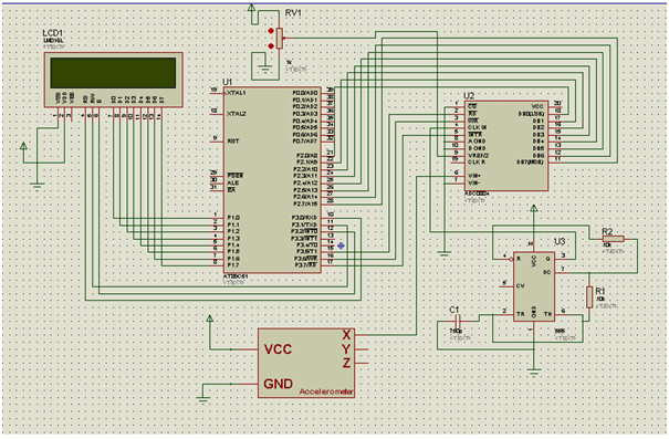
Now briefing about the circuit:

ADC’s data pins are connected to PORT 2 while its RD, WR and INT pins are connected to pin P3^5, 6 and 7 of the microcontroller respectively.

The resistor and capacitor values dealing with 555 are: R1=10K, R2=10K and C=750pF.

LCD is connected to PORT 1 with its RS, RW and E pin with pin P3^0, 1 and 2 respectively.

I have used a preset to provide a Vref/2 (2.5 V) at pin 9 of ADC.

I have also used two user defined header files: <delay.h> and <lcd.h>


  •  
 

Project Source Code

###


#include<reg51.h>
#include<delay.h>
#include<lcd.h>
sbit R=P3^5;
sbit WD=P3^6;
sbit INT=P3^7;
int read_ADC()
{
        int temp;
                                R=1;
                                WD=0;
                                WD=1;
                                while(INT==1);
                                R=1;
                                R=0;
                                temp=P2;
               return temp;
}
void main()
{
                unsigned char value='#';
                INT=1;
                P2=0xff;
                Lcd8_Init();
                while(1)
                {
                                value=read_ADC();
                                Lcd8_Cmd(0x80);
                                Lcd8_Num(value);
                                Lcd8_Write_Char(' ');                    
                }             
}


LCD.h:

#include<string.h>
//LCD Module Connections
                sbit RS=P3^0;
                sbit RW=P3^1;                                                                 
                sbit E=P3^2;
//End LCD Module Connections
char *string;
void delay(unsigned int time)
                {
                 unsigned int a,b;
                 for(a=0;a<=time;a++)
                 for(b=0;b<=128;b++);
                }
//LCD 8 Bit Interfacing Functions
void Lcd8_Cmd(unsigned char value)
                {
                P1=value;
                RS=0;
                RW=0;
                E=1;
                delay(1);
                E=0;
                }
void Lcd8_Init()
{
  Lcd8_Cmd(0x38);    //function set
  Lcd8_Cmd(0x0C);    //display on,cursor off,blink off
  Lcd8_Cmd(0x01);    //clear display
  Lcd8_Cmd(0x06);    //entry mode, set increment
}
void Lcd8_Write_Char(unsigned char value)
                {
                P1=value;
                RS=1;
                RW=0;
                E=1;
               delay(1);
                E=0;
                }
void Lcd8_Write_String(char *a)
{
                int i;
                string=a;
                for(i=0;a[i]!=' ';i++)
                Lcd8_Write_Char(a[i]);
}
void Lcd8_Num(unsigned int i)
{ unsigned char c;
int num[10],p,k=0;
if(i==0)
Lcd8_Write_Char('0');
else
{ 
while(i>0)
{
  num[k]=i%10;
  i=i/10;
  k++;
}
k--;
for (p=k;p>=0;p--)
{
  c=num[p]+48;
  P1 = c;
  RW = 0;
  RS = 1;
  E = 1;
  delay_msec(1);
  E = 0;
}
}
}

Delay.h:

void delay_msec(int time)
{
int i=0;
while(i<time)
{
TMOD=0x10;
TH1=0xfc;
TL1=0x66;
TR1=1;
while(TF1==0);
TR1=0;
TF1=0;
i++;
}
}

###


Circuit Diagrams

Circuit-Diagram-8051-Microcontroller-Interfacing-Adxl335-Accelerometer-Module

Project Video


Filed Under: Electronic Projects
Tagged With: 3-axis accelerometer, 555 timer IC, 8051, accelerometer module
 

Next Article

← Previous Article
Next Article →

Questions related to this article?
👉Ask and discuss on Electro-Tech-Online.com and EDAboard.com forums.


Tell Us What You Think!! Cancel reply

You must be logged in to post a comment.

EE TECH TOOLBOX

“ee
Tech Toolbox: Internet of Things
Explore practical strategies for minimizing attack surfaces, managing memory efficiently, and securing firmware. Download now to ensure your IoT implementations remain secure, efficient, and future-ready.

EE Learning Center

EE Learning Center
“engineers
EXPAND YOUR KNOWLEDGE AND STAY CONNECTED
Get the latest info on technologies, tools and strategies for EE professionals.

HAVE A QUESTION?

Have a technical question about an article or other engineering questions? Check out our engineering forums EDABoard.com and Electro-Tech-Online.com where you can get those questions asked and answered by your peers!


RSS EDABOARD.com Discussions

  • Voltage mode pushpull is a nonsense SMPS?
  • Input impedance matching network
  • High Side current sensing
  • The comparison of different Tcl script checkers
  • Reducing "shoot-through" in offline Full Bridge SMPS?

RSS Electro-Tech-Online.com Discussions

  • Is AI making embedded software developers more productive?
  • Back to the old BASIC days
  • Parts required for a personal project
  • PIC KIT 3 not able to program dsPIC
  • Failure of polypropylene motor-run capacitors

Featured – RPi Python Programming (27 Part)

  • RPi Python Programming 21: The SIM900A AT commands
  • RPi Python Programming 22: Calls & SMS using a SIM900A GSM-GPRS modem
  • RPi Python Programming 23: Interfacing a NEO-6MV2 GPS module with Raspberry Pi
  • RPi Python Programming 24: I2C explained
  • RPi Python Programming 25 – Synchronous serial communication in Raspberry Pi using I2C protocol
  • RPi Python Programming 26 – Interfacing ADXL345 accelerometer sensor with Raspberry Pi

Recent Articles

  • What is AWS IoT Core and when should you use it?
  • AC-DC power supply extends voltage range to 800 V DC
  • Infineon’s inductive sensor integrates coil system driver, signal conditioning circuits and DSP
  • Arm Cortex-M23 MCU delivers 87.5 µA/MHz active mode
  • STMicroelectronics releases automotive amplifiers with in-play open-load detection

EE ENGINEERING TRAINING DAYS

engineering

Submit a Guest Post

submit a guest post
Engineers Garage
  • Analog IC TIps
  • Connector Tips
  • Battery Power Tips
  • DesignFast
  • EDABoard Forums
  • EE World Online
  • Electro-Tech-Online Forums
  • EV Engineering
  • Microcontroller Tips
  • Power Electronic Tips
  • Sensor Tips
  • Test and Measurement Tips
  • 5G Technology World
  • Subscribe to our newsletter
  • About Us
  • Contact Us
  • Advertise

Copyright © 2025 WTWH Media LLC. All Rights Reserved. The material on this site may not be reproduced, distributed, transmitted, cached or otherwise used, except with the prior written permission of WTWH Media
Privacy Policy

Search Engineers Garage

  • Electronic Projects & Tutorials
    • Electronic Projects
      • Arduino Projects
      • AVR
      • Raspberry pi
      • ESP8266
      • BeagleBone
      • 8051 Microcontroller
      • ARM
      • PIC Microcontroller
      • STM32
    • Tutorials
      • Audio Electronics
      • Battery Management
      • Brainwave
      • Electric Vehicles
      • EMI/EMC/RFI
      • Hardware Filters
      • IoT tutorials
      • Power Tutorials
      • Python
      • Sensors
      • USB
      • VHDL
    • Circuit Design
    • Project Videos
    • Components
  • Articles
    • Tech Articles
    • Insight
    • Invention Stories
    • How to
    • What Is
  • News
    • Electronic Product News
    • Business News
    • Company/Start-up News
    • DIY Reviews
    • Guest Post
  • Forums
    • EDABoard.com
    • Electro-Tech-Online
    • EG Forum Archive
  • DigiKey Store
    • Cables, Wires
    • Connectors, Interconnect
    • Discrete
    • Electromechanical
    • Embedded Computers
    • Enclosures, Hardware, Office
    • Integrated Circuits (ICs)
    • Isolators
    • LED/Optoelectronics
    • Passive
    • Power, Circuit Protection
    • Programmers
    • RF, Wireless
    • Semiconductors
    • Sensors, Transducers
    • Test Products
    • Tools
  • Learn
    • eBooks/Tech Tips
    • Design Guides
    • Learning Center
    • Tech Toolboxes
    • Webinars & Digital Events
  • Resources
    • Digital Issues
    • EE Training Days
    • LEAP Awards
    • Podcasts
    • Webinars / Digital Events
    • White Papers
    • Engineering Diversity & Inclusion
    • DesignFast
  • Guest Post Guidelines
  • Advertise
  • Subscribe