Often while working with PCBs, the electronics engineers (particularly students and beginners) face a problem in dealing with the complexity of the circuit boards due to a lack of experience. Breadboards are easy to work with because there is an option to plug in and plug out the components even if you make a mistake in the connection.
However, when you switch to PCBs a lot has to be kept in mind whether it’s the soldering, de-soldering, or other related tasks. Although the constant practice is crucial to achieving the expertise level, there are a handful number of tips that can level up your chance of success.
So without beating around the bush let’s discuss some amazingly useful PCB assembly tips that we have compiled from various reliable sources.
1. Keep certain components in Spare
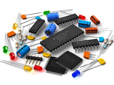
Electronics Parts (Image Courtesy: Electronics B2B)
If you are new to PCBs, it’s almost unavoidable to make mistakes with the circuit and some materials are surely going to be damaged while you are conducting experiments with the board. So, before you begin prototyping, make sure that you have ample amount of hardware in spare.
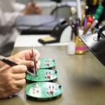
2. Be organized and sort out the tiny parts
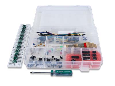
Keeping the Tiny Electronics Parts Organised (Image Courtesy: Digilent)
The complexity of PCBs, to a great extent, is associated with the fact that you have to assemble several tiny parts on an overpopulated board. So the smartest way to avoid the mess is to sort out your components as per the size or any other basis and prepare a checklist along the way. This will give you a clear idea as to what parts you have and what’s missing.
3. The Populating Order
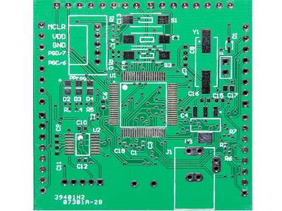
Populating Order of a PCB (Image Courtesy: Pick and Place)
There should always be a proper order to populate the board in term of direction as well as the size of the components.
Size: Many times you solder bigger components first only to realize that you don’t have ample space to place the soldering iron to solder the smaller ones which need more space. So it’s always advisable to solder the tiny parts first.
Direction: It may happen that if you are not following a directional approach and placing the parts randomly, you would forget to place some of them by the time you are done with the soldering. So, either start from right to left or left to right.
4. Use of Tweezers
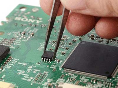
Using Tweezers to hold electronic parts while working with PCB (Image Courtesy: TDI International)
One is advised to use tweezers to handle tiny assembly components like ICs, resistors, and capacitor for the obvious reason that it offers convenience. However, picking up any electronic part with bare hands is not recommended while working with the circuit. This is because our body contains charge and that should not be transferred anywhere near your work space as that may act as an electronic interference.
5. Use of Magnifying glass
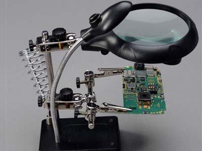
PCB Holder with Light and Magnifying Glass (Image Courtesy: AliExpress)
In order to ensure precision while handling PCBs, some magnification is always required. This is because when you make mistakes you need to troubleshoot the soldering issues like cold joints or solder bridges. So use a magnifying glass or a loupe to inspect the circuit closely.
6. Use of Poster Putty
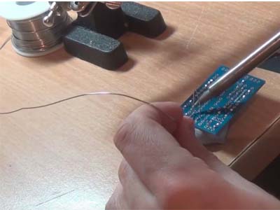
Keeping PCB in Place with Poster Putty (Image Courtesy: Make Magazine)
Often when you are soldering your circuit, you need to hold a lot of objects and at the same time keep the PCB at a required angle. Poster putty acts as a great object holder where you can just press down your PCB and it won’t move or slip away. Also, it doesn’t leave any residue on the board so you do not need to get worried about cleaning away the dirt.
7. Using a Resistor Lead Bending Tool
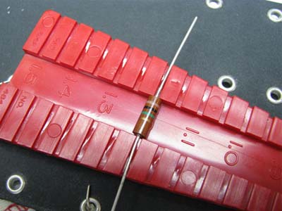
Using a Resistor Lead Bending Tool (Image Courtesy: GroupDIY)
It’s a piece of plastic built in the form of a rail that will help you specify the exact distance between two resistor leads in a circuit. Its one side offers 0.4” to 1.5” spacing for ¼ Watt resistors and the other side offers 0.5” to 1.5” spacing for ½ Watt resistors. To use it, just place the resistor at the desired space and bend it over the edges.
8. Using breadboard for header pins
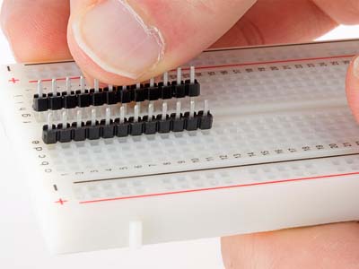
Place Header Pins on Breadboard before aligning them on PCB (Image Courtesy: SparkFun)
Before you place header pins on the PCB, insert them into a breadboard and align the PCB on top of it. After that slot the pins through the PCB holes and solder them. This will ensure that all the header pins are placed at the correct spot.
9. Glue Standoffs instead of Drilling
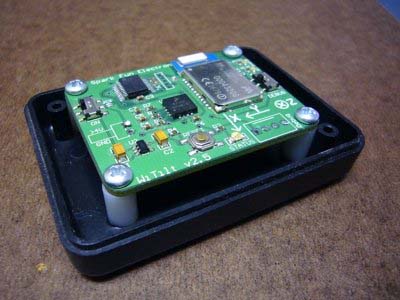
Glue Standoffs instead of drilling them on the project box (Image Courtesy: SparkFun)
Whenever you need to make a quick removable mount for your PCB-based project, there is an easy trick that makes everything much easier. Attach the stand-offs to the PCB using screws and then instead of drilling them through holes, just glue them down on a project box. The glue will be strong enough to hold the PCB permanently but if you need to make changes you may also unscrew it.
10. Start with the Ground Pin
Start with the Ground Pin while Soldering the PCB (Image Courtesy: SparkFun)
When you start the soldering procedure, it’s highly recommended to start with the ground pin and not any other pin. This is because the heat resistance capacity of the ground pin is comparatively higher than that of other pins.
If you start with power pin or any other pin that may generate heat and lead to the flow of current thus leading to a probable damage. However, starting with the ground pin will eliminate the possibility of any current flow thus reducing the chances of any kind of mishaps.
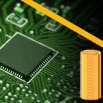
11. Select the width of the lines
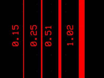
Trace width of PCB (Image Courtesy: ourpcb.com)
The width of the lines should be fixed as per the estimated current flow because if there isn’t proper space it may generate a lot of heat. So using online calculators can help in deciding the width of the lines. For power lines, the width should be more because all the current is supplied by these wires.
12. Check for allowed Wattage
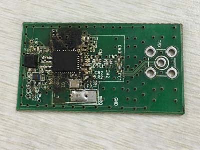
An image showing an overheated PCB
While soldering the components too much heat generation may damage the board as well as the components. The heat handling capacity of the board depends on the width of the cross-section of the board. So always look up for the allowed wattage of the board on which you are carrying out the assembly.
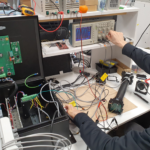
13. Accessibility of important nodes
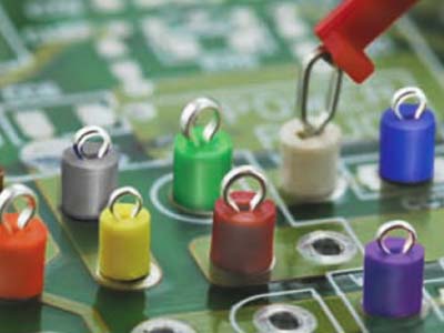
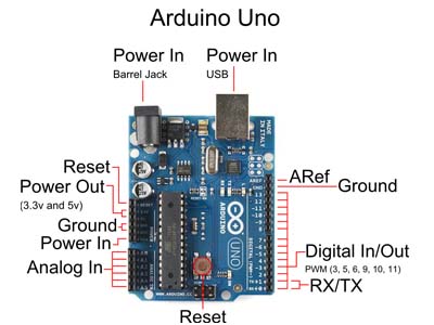
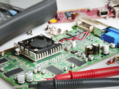
Image showing the test points for troubleshooting the PCB (Courtesy: towerfast.com)
After completing the assembly when you will be required to measure a signal for troubleshooting the circuit, you must know the nodes which are important to access. You may also add a test point connected to them.
14. Space between the components
Leave ample amount of space among the components on PCB (Image Courtesy: eBay)
If the components are packed too close to each other, there will be no room for routing of the wires. So it’s important to leave some space in between so that the wires can spread easily. Spacing not only facilitates auto-routing but will also ease the soldering procedure.
15. Avoid Cold Solder Joints
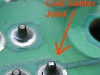
Picture depicting a cold solder joint (Image Courtesy: Allpar)
Sometimes while soldering the applied heat is not enough for the solder to melt properly or the surface is not clean. Often it may also happen that the hot solder flows into a cold joint and form a blob of gray solder that is not attached to the joint. In all such situations, a cold solder joint is formed that can cause static noises or intermittent cutouts.
To counter this issue, one has to either remelt the existing solder or suck it out and clean the spot before re-soldering. If you wish to avoid such cases, it is advised to heat the soldering iron tip and then touch the joint with the solder. This will help in melting the solder which will then flow and engulf the joint properly. One can also add some flux (a chemical agent) to the surface so that the hot solder immediately sticks to the pin.
Conclusion
The main aim of this compilation is to present a brief guideline for the beginners who are either going to or just recently switched from breadboards to PCBs. Although these are some of the useful circuit board assembly tips gathered from our sources, there may be more which haven’t been covered here. So if you have any other tips feel free to mention them in the comments section below.
You may also like:


Filed Under: Tech Articles
Questions related to this article?
👉Ask and discuss on Electro-Tech-Online.com and EDAboard.com forums.
Tell Us What You Think!!
You must be logged in to post a comment.