Engineers Garage

  • Electronic Projects & Tutorials
    • Electronic Projects
      • Arduino Projects
      • AVR
      • Raspberry pi
      • ESP8266
      • BeagleBone
      • 8051 Microcontroller
      • ARM
      • PIC Microcontroller
      • STM32
    • Tutorials
      • Audio Electronics
      • Battery Management
      • Brainwave
      • Electric Vehicles
      • EMI/EMC/RFI
      • Hardware Filters
      • IoT tutorials
      • Power Tutorials
      • Python
      • Sensors
      • USB
      • VHDL
    • Circuit Design
    • Project Videos
    • Components
  • Articles
    • Tech Articles
    • Insight
    • Invention Stories
    • How to
    • What Is
  • News
    • Electronic Product News
    • Business News
    • Company/Start-up News
    • DIY Reviews
    • Guest Post
  • Forums
    • EDABoard.com
    • Electro-Tech-Online
    • EG Forum Archive
  • DigiKey Store
    • Cables, Wires
    • Connectors, Interconnect
    • Discrete
    • Electromechanical
    • Embedded Computers
    • Enclosures, Hardware, Office
    • Integrated Circuits (ICs)
    • Isolators
    • LED/Optoelectronics
    • Passive
    • Power, Circuit Protection
    • Programmers
    • RF, Wireless
    • Semiconductors
    • Sensors, Transducers
    • Test Products
    • Tools
  • Learn
    • eBooks/Tech Tips
    • Design Guides
    • Learning Center
    • Tech Toolboxes
    • Webinars & Digital Events
  • Resources
    • Digital Issues
    • EE Training Days
    • LEAP Awards
    • Podcasts
    • Webinars / Digital Events
    • White Papers
    • Engineering Diversity & Inclusion
    • DesignFast
  • Guest Post Guidelines
  • Advertise
  • Subscribe

Interfacing Latches(74ls574,74ls373) Flip flops with 8051 (89c51, 89c52) Microcontroller

By EG Projects February 13, 2021

In this project i am going to interface latches with 8051(89c51, 89c52) microcontroller. I am going to interface  74LS574 with 8051(89c51, 89c52). You can also interface any other latch(74ls373, 74ls374 etc) with a slight changes in the connections given in the circuit diagram. The whole project is about, grabbing the status of the latches  inputs and then display them on 40×4 character lcd screen when needed.

What is Latche?

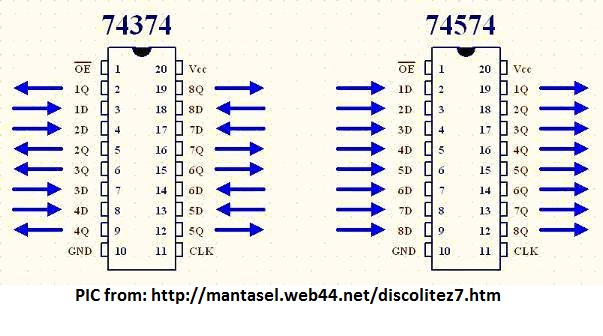
what is latch? A latch is a flip flop or combination of flip flops that can store data bits in it. A single flip flop can store a single bit information at a time. Latches are used to build sequential circuits. The latch which i am using in this tutorial is 74ls574. It is an 8-bit latch, which means it can store 8-bit information at a time. It has 20 pins. One vcc apply +5v to it. GND make it ground. 8 input-pins and 8 output-pins. Two most important pins of the latches are OE and CP.

  • CP- CP is clock Pulse. When CP is supplied with Low to High pulse (L-H) then the data on the input pins are stored in the internal flip flops of the latch.
  • OE- OE is enable latch. When OE is made ‘0’ data stored in the flip flops appeared on the output pins. When its 1 nothing will appear on the output its void or GND.
Important note: When i was working with this particular latch. what i noted is when you leave any latch input pin void, means nothing is connected on the input pin. The output for that particular pin will appear high. I think in default state output pins are normally high. So be sure if you are not using any input pin then ground it properly. Don’t let your circuit floating.

I used 74ls574 because of its simple one direction input and one direction output. The pic below clearly clears the concept.  

74ls574 and 74ls374 pinout

74ls574 and 74ls374 pinout

What the project is doing?

Four Latches are used in the project. They grab information from external inputs and then one by one pass it to 8051 microcontroller. Which then displays the latch output on 40×4 character lcd. All latches output are connected to Port-0 of 89c52 microcontroller.

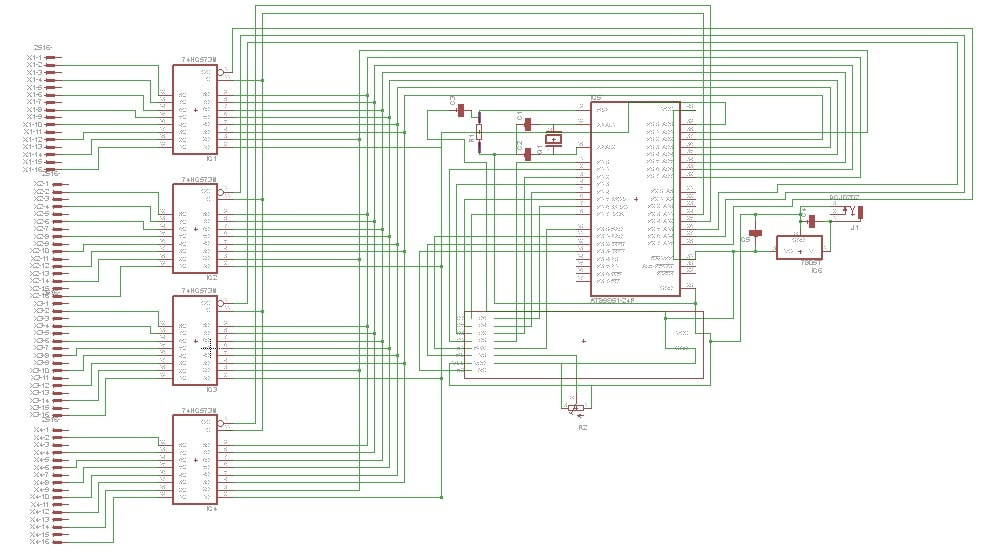
8051 Latch interface – Project Circuit

Microcontroller used in the Project is 89c52 microcontroller. 11.0592 MHz crystal is used in the project to generate clock pulses for microcontroller operation. 40×4 character lcd is interfaced in 8-bit mode with 89c51 microcontroller. Data pins of Lcd are connected to Port-1 of 89c52. Lcd controlling pins RS(Register-Select) is connected to Port-3 Pin#2. RW(Read-Write) is connected to Port-3 Pin#0. Enable for first HD44780 lcd controller is connected to Port-3 Pin#1. Enable for second HD44780 lcd controller is connected to Port-3 Pin#3.

Latches are enabled using Port-2. Port-2 Pin#4 enables first latch Pin#5 second Pin#6 third and Pin#7 fourth. All the latches are connected to Common Clock. CP is provided using Port-2 Pin#3.

Latches with 8051 microcontroller

Latches with 8051 microcontroller
The above circuit diagram is not clear. It is made in proteaus circuit simulator.  I uploaded the proteaus files here so you can easily view the circuit by your self in proteaus.

Circuit Diagram in Proteaus

I also designed the PCB of above circuit. Final PCB circuit with electronic components installed on it is below. I etched the circuit manually by hand using etching chemical. PCB hole drilling and components soldering on PCB is also carried out manually at home. Jumper wires are input to the latches. Output is directly connected to 8051 microcontroller registers. See the bottom half traces of PCB.

Latches interfaced with 89c51 microcontroller final PCB

Latches interfaced with 89c51 microcontroller final PCB

89c51 latches interface back side of PCB

89c51 latches interface back side of PCB

Project working principle

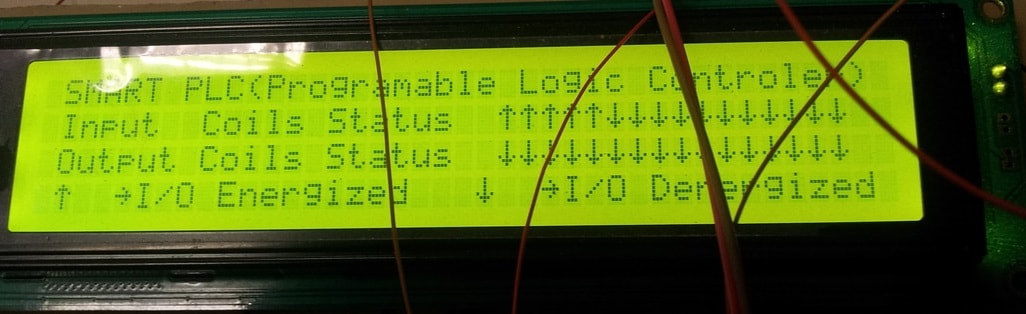
For high input(1) at latch an upward arrow will be displayed on lcd for that particular input. For Low input(0) at latch a downward arrow will be displayed on lcd for that particular input. Upward and Downward arrows are generated in CG-RAM of lcd. They are not text so we first have to create them. I first created them in CG-RAM(Character Generated RAM) of lcd then i displayed them on lcd where needed.

  • String displayed on Lcd first       line is ” SMART PLC(Programable Logic Controler)“.
  • String displayed on Lcd second line is  1st and 2nd Latch status (Upwards Downwards Arrows) 
  • String displayed on Lcd third      line is  3rd and 4th Latch status (Upwards Downwards Arrows)
  • String displayed on Lcd fourth    line is “I/O Energized   I/O Denergized“.

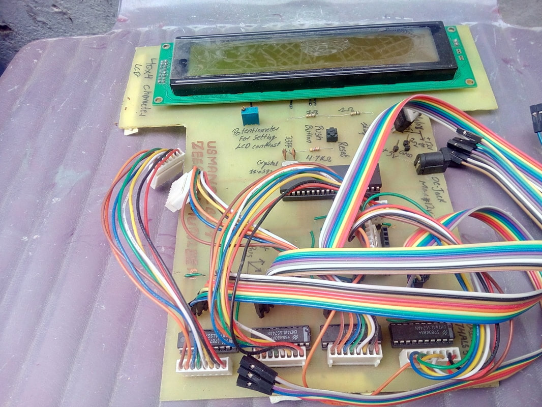
Final latches status on lc screen by 8051 microcontroller

Final output displayed on lcd screen. Latches status are displayed on 2 and 3rd rows. Arrow up ward means latch is active. At latch input voltage(5 volts) is present. Arrow pointing downwards means no voltage(0 v) on the input of latch. 

Latches with 8051 and 40x4 lcd display

Latches with 8051 and 40×4 lcd display
This project was a sub part of a larger project. I designed a PLC(Programmable logic controller) using microcontrollers. The latches with 8051 microcontroller is actually the status board in PLC project. Output from the main board is feed to latches as input and then the status of individual pins are displayed on lcd. I recommend you to take a look at PLC project. You can take PLC project as your electronics major final year project.

DIY PLC with Microcontroller

Download the project files, Codes and Simulation, folder contains the project hex code and other keil uvision files. Simulation of the project is also present in the folder. Simulation is made in Proteaus 8.0 You can write your Quires below.
Latches with 89c51 Microcontroller

You may also like:


  • What are the top development boards for AI and ML?

  • What are top applications of CAN protocol?

  • What types of motors are used in electric vehicles?

  • What to expect from microcontrollers in 2023
  • battery selection low power design
    What are the battery-selection criteria for low-power design?

  • What are field-programmable gate arrays (FPGAs)?

Filed Under: 8051 Microcontroller, Electronic Projects, Featured Contributions, Microcontroller Projects


Next Article

← Previous Article
Next Article →

Questions related to this article?
👉Ask and discuss on Electro-Tech-Online.com and EDAboard.com forums.


Tell Us What You Think!! Cancel reply

You must be logged in to post a comment.

EE TECH TOOLBOX

“ee
Tech Toolbox: Internet of Things
Explore practical strategies for minimizing attack surfaces, managing memory efficiently, and securing firmware. Download now to ensure your IoT implementations remain secure, efficient, and future-ready.

EE Learning Center

EE Learning Center
“engineers
EXPAND YOUR KNOWLEDGE AND STAY CONNECTED
Get the latest info on technologies, tools and strategies for EE professionals.

HAVE A QUESTION?

Have a technical question about an article or other engineering questions? Check out our engineering forums EDABoard.com and Electro-Tech-Online.com where you can get those questions asked and answered by your peers!


RSS EDABOARD.com Discussions

  • Reducing "shoot-through" in offline Full Bridge SMPS?
  • High Side current sensing
  • How to simulate power electronics converter in PSpice?
  • Voltage mode pushpull is a nonsense SMPS?
  • Layout IRN reduction in Comparator

RSS Electro-Tech-Online.com Discussions

  • Back to the old BASIC days
  • Parts required for a personal project
  • PIC KIT 3 not able to program dsPIC
  • Failure of polypropylene motor-run capacitors
  • Siemens large industrial PLC parts

Featured – RPi Python Programming (27 Part)

  • RPi Python Programming 21: The SIM900A AT commands
  • RPi Python Programming 22: Calls & SMS using a SIM900A GSM-GPRS modem
  • RPi Python Programming 23: Interfacing a NEO-6MV2 GPS module with Raspberry Pi
  • RPi Python Programming 24: I2C explained
  • RPi Python Programming 25 – Synchronous serial communication in Raspberry Pi using I2C protocol
  • RPi Python Programming 26 – Interfacing ADXL345 accelerometer sensor with Raspberry Pi

Recent Articles

  • What is AWS IoT Core and when should you use it?
  • AC-DC power supply extends voltage range to 800 V DC
  • Infineon’s inductive sensor integrates coil system driver, signal conditioning circuits and DSP
  • Arm Cortex-M23 MCU delivers 87.5 µA/MHz active mode
  • STMicroelectronics releases automotive amplifiers with in-play open-load detection

EE ENGINEERING TRAINING DAYS

engineering

Submit a Guest Post

submit a guest post
Engineers Garage
  • Analog IC TIps
  • Connector Tips
  • Battery Power Tips
  • DesignFast
  • EDABoard Forums
  • EE World Online
  • Electro-Tech-Online Forums
  • EV Engineering
  • Microcontroller Tips
  • Power Electronic Tips
  • Sensor Tips
  • Test and Measurement Tips
  • 5G Technology World
  • Subscribe to our newsletter
  • About Us
  • Contact Us
  • Advertise

Copyright © 2025 WTWH Media LLC. All Rights Reserved. The material on this site may not be reproduced, distributed, transmitted, cached or otherwise used, except with the prior written permission of WTWH Media
Privacy Policy

Search Engineers Garage

  • Electronic Projects & Tutorials
    • Electronic Projects
      • Arduino Projects
      • AVR
      • Raspberry pi
      • ESP8266
      • BeagleBone
      • 8051 Microcontroller
      • ARM
      • PIC Microcontroller
      • STM32
    • Tutorials
      • Audio Electronics
      • Battery Management
      • Brainwave
      • Electric Vehicles
      • EMI/EMC/RFI
      • Hardware Filters
      • IoT tutorials
      • Power Tutorials
      • Python
      • Sensors
      • USB
      • VHDL
    • Circuit Design
    • Project Videos
    • Components
  • Articles
    • Tech Articles
    • Insight
    • Invention Stories
    • How to
    • What Is
  • News
    • Electronic Product News
    • Business News
    • Company/Start-up News
    • DIY Reviews
    • Guest Post
  • Forums
    • EDABoard.com
    • Electro-Tech-Online
    • EG Forum Archive
  • DigiKey Store
    • Cables, Wires
    • Connectors, Interconnect
    • Discrete
    • Electromechanical
    • Embedded Computers
    • Enclosures, Hardware, Office
    • Integrated Circuits (ICs)
    • Isolators
    • LED/Optoelectronics
    • Passive
    • Power, Circuit Protection
    • Programmers
    • RF, Wireless
    • Semiconductors
    • Sensors, Transducers
    • Test Products
    • Tools
  • Learn
    • eBooks/Tech Tips
    • Design Guides
    • Learning Center
    • Tech Toolboxes
    • Webinars & Digital Events
  • Resources
    • Digital Issues
    • EE Training Days
    • LEAP Awards
    • Podcasts
    • Webinars / Digital Events
    • White Papers
    • Engineering Diversity & Inclusion
    • DesignFast
  • Guest Post Guidelines
  • Advertise
  • Subscribe