Engineers Garage

  • Electronic Projects & Tutorials
    • Electronic Projects
      • Arduino Projects
      • AVR
      • Raspberry pi
      • ESP8266
      • BeagleBone
      • 8051 Microcontroller
      • ARM
      • PIC Microcontroller
      • STM32
    • Tutorials
      • Audio Electronics
      • Battery Management
      • Brainwave
      • Electric Vehicles
      • EMI/EMC/RFI
      • Hardware Filters
      • IoT tutorials
      • Power Tutorials
      • Python
      • Sensors
      • USB
      • VHDL
    • Circuit Design
    • Project Videos
    • Components
  • Articles
    • Tech Articles
    • Insight
    • Invention Stories
    • How to
    • What Is
  • News
    • Electronic Product News
    • Business News
    • Company/Start-up News
    • DIY Reviews
    • Guest Post
  • Forums
    • EDABoard.com
    • Electro-Tech-Online
    • EG Forum Archive
  • DigiKey Store
    • Cables, Wires
    • Connectors, Interconnect
    • Discrete
    • Electromechanical
    • Embedded Computers
    • Enclosures, Hardware, Office
    • Integrated Circuits (ICs)
    • Isolators
    • LED/Optoelectronics
    • Passive
    • Power, Circuit Protection
    • Programmers
    • RF, Wireless
    • Semiconductors
    • Sensors, Transducers
    • Test Products
    • Tools
  • Learn
    • eBooks/Tech Tips
    • Design Guides
    • Learning Center
    • Tech Toolboxes
    • Webinars & Digital Events
  • Resources
    • Digital Issues
    • EE Training Days
    • LEAP Awards
    • Podcasts
    • Webinars / Digital Events
    • White Papers
    • Engineering Diversity & Inclusion
    • DesignFast
  • Guest Post Guidelines
  • Advertise
  • Subscribe

Rechargeable toy car with push-to-start/hold-to-stop functionality

By By Irena Zhuravchak, Technical Documentation Apps Engineer, and Volodymyr Ilchuk, Team Lead of Applications Engineering, Renesas Electronics, Lviv, Ukraine June 6, 2023

This article describes how to create a rechargeable toy car with push-to-start / hold-to-stop (Figure 1) using HVPAK™ SLG47105. The following design provides constant voltage on the motor, regardless of the battery charge and Push-to-Start / Hold-to-Stop capability. Thanks to the Hold-to-Stop functionality, the car automatically turns off when it’s stuck. So, if the child directs it somewhere and forgets about the toy, the car will switch off and will not consume more power, thus saving the battery. The CC-CV battery charger control is also implemented.

Only one SLG47105 and a few extra components allow the creation of a complete device with charging control, motor driving, overcurrent protection, and other interface features.

Figure 1: A Prototype of a Toy Car

Operating principle
The full circuit schematic is presented in Figure 2.

Figure 2: Full circuit schematic

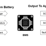
The brushed DC motor is used for this project. If the car is pushed, SLG47105 detects it, and the car starts driving. If it is held, the system powers down. The device is powered with a 3.7 V Li-ion Battery. When the USB charger is connected, the SLG47105 detects the voltage level, and the appropriate stage of CC-CV charging begins. The motor is blocked during charging.

There are also three LEDs to notify about the process.

LED1 (RED) is CHARGE. Blinking represents the charging process. The LED is ON when the charge is complete. The LED is OFF when no USB is connected.
LED2 (BLUE) is STATUS. If VBAT < 3 V – blinking. If VBAT > 3 V – the LED is ON if the car drives and the LED is OFF when the car doesn’t move.
LED3 (BLUE&RED) blinking means car movement.

The proposed PCB design is shown in Figure 3.

Figure 3: HVPAK Demo Car PCB

The GreenPAK Design consists of two parts: Car Motor Control and USB Charger. The design file can be downloaded here Rechargeable Toy Car with Push-to-Start/Hold-to-Stop Functionality.hvp. It was created in free GUI-based Go Configure™ Software Hub | Renesas.

The Motor Control part is shown in Figure 4.

Figure 4: Car motor GreenPAK design

The PWM0 block provides a ~50 kHz signal with a PWM depending on the load voltage at the motor. The HV_GPO0_HD and HV_GPO1_HD of the Differential Amplifier with Integrator and Comparator are connected to Diff+ and Diff- of HV OUT CTRL0 (first Full Bridge). This macrocell is useful when there is a need to keep the constant voltage at the Full Bridge load. The integrated DC voltage level is applied to the comparator`s negative input. The comparator outputs are used to control the PWM duty cycle. In this case, a closed loop system controls the PWM duty cycle to ensure the constant average output voltage level.

The ACMP1H is connected to the M- motor terminal and checks if the car was pushed. When the shaft of the DC Motor rotates in the coil according to the electromagnetic induction law, an electromotive force (EMF) is induced. This signal is detected by ACMP1H. Its output goes to DFF13 which then enables the PWM0 block. 4-bit LUT1 provides an Enable signal for LED3 when the car is ON. To avoid battery discharge ACMP1H is connected to the 50 ms Wake Sleep Controller.

When the shaft of the DC Motor is held to stop, the current increases. The CCMP1 is connected to the Sense A resistor (PIN5) and monitors the current. Its output goes to MF1 which detects exceeding the limit of this current. If it lasts longer than 500 ms (CNT1/DLY1), the HIGH signal from 4-bit LUT0 resets the DFF13, and the system is powered down. The HV OUT CTRL0 is powered down with a 300 ms delay to give the motor some time to stop and avoid restarting the system. Also, the VUSB detect signal is connected to 4-bit LUT0, so if it is HIGH (the USB is connected), the system is powered down as well.

MF3 and PGEN provide controlling and selecting functions for LED1 and LED2 described in Section 1. The USB Charger part is presented in Figure 5.

Figure 5: USB Charger GreenPAK design

If the Vusb is connected, PIN3 detects it and powers ON the ACMP0H. The ACMP0H checks the Vbat voltage. DFF6’s output is HIGH, so no voltage divider is connected to PIN19 (IN+ Source with x8 gain of the ACMP0H). If Vbat is lower than 3 V, the Pre-Charging stage starts. PWM1 sets the current and CCMP1 controls it. In this case, the Up/Down input of the PWM1 macrocell is LOW, which means that we start charging from Vref = 160 mV for CCMP1 Vref (Figure 6). As a result, the CCMP1 maintains the 67 mA current:

As soon as the ACMP0H output is HIGH (the Vbat is higher than 3.0 V), the DFF6 output goes to LOW, and the voltage divider is connected to PIN19. The Constant Current phase starts. In this case, the ACMP0H makes a comparison for 4.2 V (not 3.0 V as in 1st case). The Up/Down input of the PWM1 is HIGH, so the CCMP1 Vref is 960 mV. The resulting current is ~ 400 mA. Note that these current limits can be changed by changing the Vref value in the Reg File or by changing the resistor connected to the PIN 12 (Sense B).

This CC phase continues until the battery voltage reaches 4.2 V (ACMP0H output is HIGH). Then the Constant Current stops, and the Constant Voltage phase starts. The Up/Down input of the PWM1 is LOW, so the CCMP1 Vref is 160 mV. In this case, the ACMP0H controls the constant voltage of 4.2 V, and the CCMP1 just checks and keeps the current decreasing and lower than the IBF of 67 mA until the battery is fully charged. When the battery is fully charged, the charging process stops, and all corresponding blocks are in Sleep Mode (CHG_Sleep is HIGH).

Figure 6: CCMP1 Vref reg file data

Device testing
Please, see also the video of the working Rechargeable Toy Car with Push-to-Start / Hold-to-Stop Functionality.

The following Figures 7-12 show the signal on the motor terminal depending on VDD (Vbat).

Figure 7: VDD = 3.0 V, duty cycle 43%

Figure 8: VDD = 3.4 V, duty cycle 40%

Figure 9: VDD = 3.4 V, duty cycle 40%

Figure 10: VDD = 3.7 V, duty cycle 35%

Figure 11: VDD = 4.2 V, duty cycle 31%

Figure 12: Peak on PIN20 (M- terminal) during Push-to-Start

Conclusion
This article describes how to configure the HVPAK to create a rechargeable toy car with push-to-start / hold-to-stop functionality. The results prove that the circuit works as expected, and the SLG47105 is capable of acting as the control module for the Brushed DC Motor and 3.7 V Li-ion Battery charger at the same time.

The GreenPAK’s internal resources, including the HV, oscillators, logic, and GPIOs are easy to configure to implement the desired functionality for this design.

You may also like:

  • battery cycles
    How rechargeable batteries, charging, and discharging cycles work

  • Understanding battery management systems

  • What battery chemistries are used in electric vehicles?

  • What types of motors are used in electric vehicles?

  • What is Wireless Electric Vehicle Charging System (WEVCS)?
  • battery selection low power design
    What are the battery-selection criteria for low-power design?

Filed Under: Battery Management, Electronic Projects, Tutorials


Next Article

← Previous Article
Next Article →

Questions related to this article?
👉Ask and discuss on EDAboard.com and Electro-Tech-Online.com forums.


Tell Us What You Think!! Cancel reply

You must be logged in to post a comment.

EE TECH TOOLBOX

“ee
Tech Toolbox: Internet of Things
Explore practical strategies for minimizing attack surfaces, managing memory efficiently, and securing firmware. Download now to ensure your IoT implementations remain secure, efficient, and future-ready.

EE Learning Center

EE Learning Center
“engineers
EXPAND YOUR KNOWLEDGE AND STAY CONNECTED
Get the latest info on technologies, tools and strategies for EE professionals.

HAVE A QUESTION?

Have a technical question about an article or other engineering questions? Check out our engineering forums EDABoard.com and Electro-Tech-Online.com where you can get those questions asked and answered by your peers!


RSS EDABOARD.com Discussions

  • Reducing "shoot-through" in offline Full Bridge SMPS?
  • High Side current sensing
  • How to simulate power electronics converter in PSpice?
  • Voltage mode pushpull is a nonsense SMPS?
  • Layout IRN reduction in Comparator

RSS Electro-Tech-Online.com Discussions

  • Back to the old BASIC days
  • Parts required for a personal project
  • PIC KIT 3 not able to program dsPIC
  • Failure of polypropylene motor-run capacitors
  • Siemens large industrial PLC parts

Featured – RPi Python Programming (27 Part)

  • RPi Python Programming 21: The SIM900A AT commands
  • RPi Python Programming 22: Calls & SMS using a SIM900A GSM-GPRS modem
  • RPi Python Programming 23: Interfacing a NEO-6MV2 GPS module with Raspberry Pi
  • RPi Python Programming 24: I2C explained
  • RPi Python Programming 25 – Synchronous serial communication in Raspberry Pi using I2C protocol
  • RPi Python Programming 26 – Interfacing ADXL345 accelerometer sensor with Raspberry Pi

Recent Articles

  • What is AWS IoT Core and when should you use it?
  • AC-DC power supply extends voltage range to 800 V DC
  • Infineon’s inductive sensor integrates coil system driver, signal conditioning circuits and DSP
  • Arm Cortex-M23 MCU delivers 87.5 µA/MHz active mode
  • STMicroelectronics releases automotive amplifiers with in-play open-load detection

EE ENGINEERING TRAINING DAYS

engineering

Submit a Guest Post

submit a guest post
Engineers Garage
  • Analog IC TIps
  • Connector Tips
  • Battery Power Tips
  • DesignFast
  • EDABoard Forums
  • EE World Online
  • Electro-Tech-Online Forums
  • EV Engineering
  • Microcontroller Tips
  • Power Electronic Tips
  • Sensor Tips
  • Test and Measurement Tips
  • 5G Technology World
  • Subscribe to our newsletter
  • About Us
  • Contact Us
  • Advertise

Copyright © 2025 WTWH Media LLC. All Rights Reserved. The material on this site may not be reproduced, distributed, transmitted, cached or otherwise used, except with the prior written permission of WTWH Media
Privacy Policy

Search Engineers Garage

  • Electronic Projects & Tutorials
    • Electronic Projects
      • Arduino Projects
      • AVR
      • Raspberry pi
      • ESP8266
      • BeagleBone
      • 8051 Microcontroller
      • ARM
      • PIC Microcontroller
      • STM32
    • Tutorials
      • Audio Electronics
      • Battery Management
      • Brainwave
      • Electric Vehicles
      • EMI/EMC/RFI
      • Hardware Filters
      • IoT tutorials
      • Power Tutorials
      • Python
      • Sensors
      • USB
      • VHDL
    • Circuit Design
    • Project Videos
    • Components
  • Articles
    • Tech Articles
    • Insight
    • Invention Stories
    • How to
    • What Is
  • News
    • Electronic Product News
    • Business News
    • Company/Start-up News
    • DIY Reviews
    • Guest Post
  • Forums
    • EDABoard.com
    • Electro-Tech-Online
    • EG Forum Archive
  • DigiKey Store
    • Cables, Wires
    • Connectors, Interconnect
    • Discrete
    • Electromechanical
    • Embedded Computers
    • Enclosures, Hardware, Office
    • Integrated Circuits (ICs)
    • Isolators
    • LED/Optoelectronics
    • Passive
    • Power, Circuit Protection
    • Programmers
    • RF, Wireless
    • Semiconductors
    • Sensors, Transducers
    • Test Products
    • Tools
  • Learn
    • eBooks/Tech Tips
    • Design Guides
    • Learning Center
    • Tech Toolboxes
    • Webinars & Digital Events
  • Resources
    • Digital Issues
    • EE Training Days
    • LEAP Awards
    • Podcasts
    • Webinars / Digital Events
    • White Papers
    • Engineering Diversity & Inclusion
    • DesignFast
  • Guest Post Guidelines
  • Advertise
  • Subscribe