Several consumer devices now involve temperature monitoring. For example, most of the air conditioners on the market feature climate control, where the AC continuously monitors the ambient temperature of a room and accordingly regulates the air conditioning. Even some digital clocks now have temperature monitors embedded in them. Many other consumer appliances also offer temperature monitoring.
In this project, we’ve built a temperature sensor using Arduino and the LM35 temperature sensor. The LM35 can be used to sense ambient and surface temperatures.
The purpose of the sensor built here is to monitor the ambient temperature of a room over a cycle of 24 hours and display the current temperature, the maximum temperature recorded, and the minimum temperature recorded within that 24-hour cycle on a LCD panel.
Components required:
1. Arduino UNO x1
2. A 16×2 character LCD x1
3. A 10K Pot x1
4. A 330 Ohms Resistor or any low-value resistor x1
5. An LM35 Sensor x1
6. A breadboard x1
7. Male-to-male jumper or connecting wires
Circuit diagram:
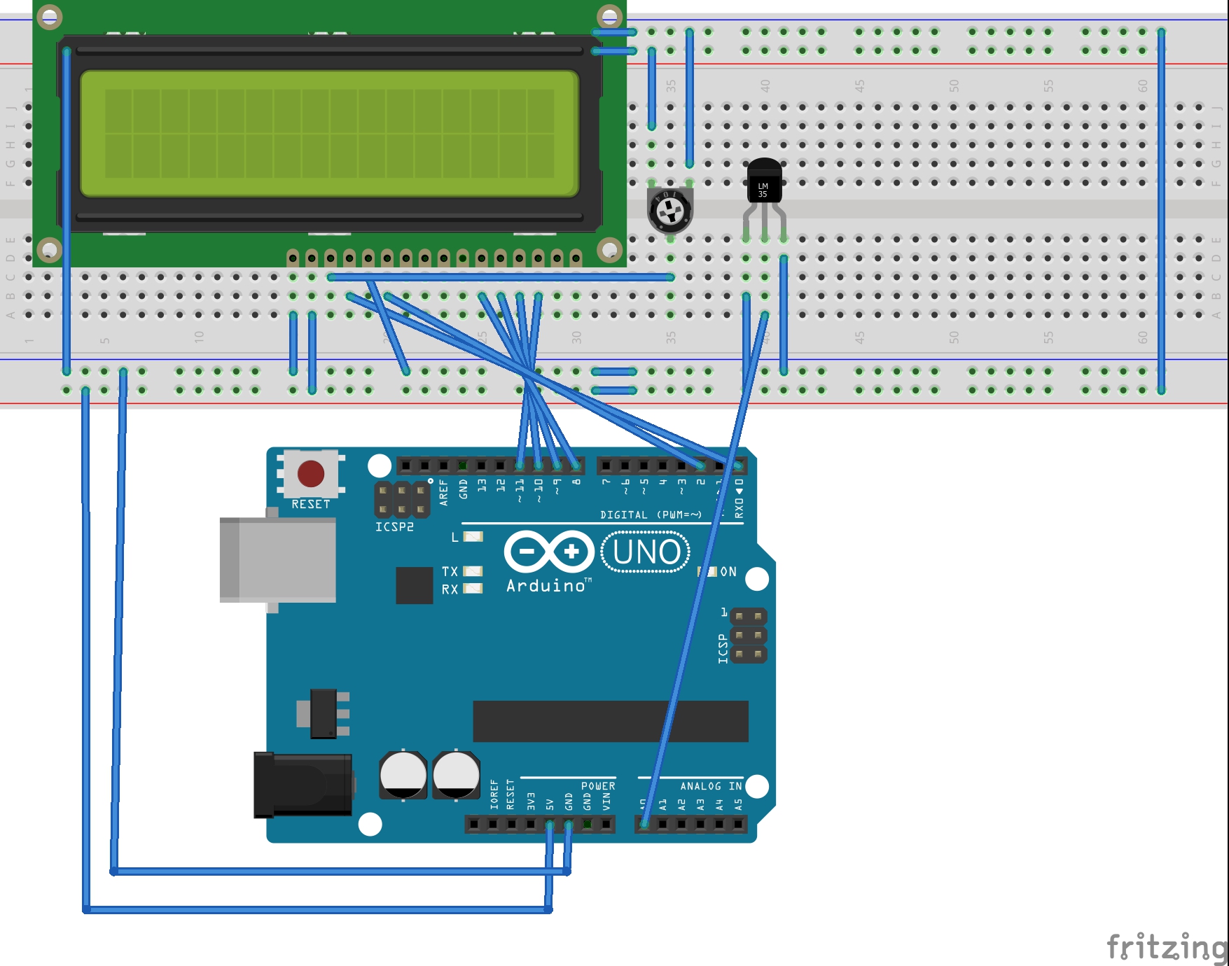
Circuit connections
The temperature monitor built in this project uses an LM35 temperature sensor. A 16×2 character LCD displays the current, maximum, and minimum temperatures recorded over a 24-hour cycle.
The circuit is designed by interfacing the LM35 and the character LCD with Arduino UNO.
The LM35 series includes sensors, such as LM35, LM35A, LM35CA, LM35C, and LM35D. The sensor used is the LM35 in the TO-92 LP package. In this packaging, the sensor comes as a three-terminal device. From the front view, the far-left terminal provides the power supply, the middle terminal offers the analog output, and the far-right terminal is the sensor ground.
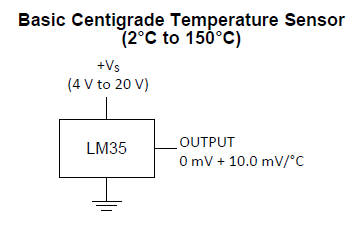
 In the circuit, the sensor receives a single power supply from Arduino. The sensor’s analog output is connected to the A0 analog input pin of Arduino UNO. In this circuit configuration, the LM35 acts as the basic centigrade temperature sensor. It outputs the analog voltage directly proportional to the temperature in a positive range (2˚ to 150˚C).
To display the current, minimum, and maximum recorded temperatures, a 16×2 character LCD JHD162A is interfaced with Arduino UNO. The 16-pin LCD module is interfaced in a 4-bit mode.
- Pin 1 (GND) and 16 (LED) of the LCD module are connected to the ground.
- Pin 2 (VCC) is connected to the VCC.
- Pin 15 (LED+) of the LCD module is connected to the VCC via a small-value resistor.
- Pin 3 (VEE) is connected to the variable terminal of a pot while the fixed terminals of the pot are connected to the ground and the VCC.
- The R/W pin is connected to the ground as Arduino will only write data to the LCD module.
- The RS, EN, DB4, DB5, DB6, and DB7 pins of LCD are connected to pins 0, 2, 8, 9, 10, and 11 of Arduino UNO, respectively.
The circuit is assembled on a breadboard. The breadboard is supplied a common ground and 5V supply rail from one of the ground pins and the 5V pin of Arduino UNO.
Arduino sketch
How the project works
The LM35 is a general-purpose temperature sensor from Texas Instruments. The series comprises of the LM35, LM35A, LM35CA, LM35C, and LM35D sensors.
The LM35 sensor used in this circuit can sense a temperature ranging from -55˚ to 150˚C. It’s also internally calibrated to centigrade scaling and gives an output voltage directly proportional to the centigrade temperature. The sensor output has an accuracy of +/-0.25˚C at room temperature and +/-0.75˚C at full scale.

The LM35 sensor receives a plus-minus power supply from Arduino. Its analog output is connected to the A0 pin of Arduino UNO.
Arduino is programmed to sample the analog voltage from the sensor to obtain the temperature reading. From the LM35 datasheet, it can be found that on startup, the output of the sensor stabilizes within 40 uSEC. As the sensor is supplied with a constant DC voltage of 5V, a stable analog output from the sensor is expected.
The LM35 sensor can be configured as a basic centigrade or a full-scale centigrade temperature sensor in a circuit.
As the basic centigrade temperature sensor, the LM35 must be configured according to this circuit diagram:
As a full-scale centigrade temperature sensor, the LM35 must be configured according to this circuit diagram:
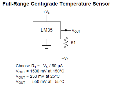
The sensor will gain 10mV per degree of centigrade. In a full-scale configuration, the sensor gain is obtained in reverse polarity to the negative temperatures.
The temperature can be derived from the voltage output according to this equation:
Temperature (in ˚C) = LM35 Output Voltage (in Milli-Volt)/10
When using Arduino, the LM35 cannot be configured as a full-scale centigrade temperature sensor as the analog pins on the Arduino board can only sense unipolar voltages. Therefore, the sensor must be configured as a basic centigrade temperature sensor, where it senses and measures temperature ranges from 2˚ to 150˚C.
For a given temperature range, the analog output of the sensor should be from 20mV to 1.5V. At room temperature (25˚C), the output of the sensor should be 250 mV.
It’s ideal to take large number of voltage samples from the sensor and derive a mean value as the final result. This is because of the breadboard connections, the supply fluctuations of the sensor, and other operational factors.
When taking significant numbers of voltage samples, a constant mean value of the temperature can be obtained — which can be used as a reliable temperature reading from the sensor.
The temperature monitor designed here does more than just sense the current ambient temperature, however. It also keeps a record of the temperature over a 24-hour cycle, interpreting the minimum and maximum temperature over an entire day.
But rather than logging the temperatures over an extended period to figure out the maximum and minimum temperatures, Arduino is programmed to compare the recently recorded temperatures with the previously recorded temperatures.
The device records the first temperature reading, which involves taking 4,000 consecutive voltage samples from the LM35. The mean value of these samples is then used to record the first temperature after the device is powered on. About four times the number of voltage samples taken for first reading are required to ensure a stable mean value. This number of samples is taken for a reliable reading after the start-up.
Arduino uses the analog voltage at the A0 pin and converts it to a 10-bit digital value, ranging from 0 to 1023, using the internal ADC. The value of the analog voltage can be obtained by multiplying the ADC value by a reference voltage (which is 5V in this case) and dividing the expression by 1024.
Analog Voltage = ADC Value * Analog Reference / 1024
= ADC Value * 5V/1024
As the sensor gains 10mV per degree of centigrade, the analog voltage (in mV when divided by 10), gives the temperature in degree Celsius. As the derived voltage from the sensor is in Volts, the analog voltage reading must be multiplied by 1,000 to convert it to mV, and then is divided by 10 to get the correct temperature reading.
The value of the temperature is obtained by this equation:
Temperature (˚C) = Analog Voltage (V) * 100
After recording the first temperature reading, the current, last recorded, minimum, and maximum temperatures are also set. Next, Arduino is programmed to take a temperature reading every second. Therefore, a loop is run than iterates for 86,400 times (24 hours x 60 minutes x 60 seconds).
In each iteration, the temperature from the LM35 sensor is recorded by taking 1,000 consecutive voltage samples from the sensor. A mean value of these samples is then recorded to obtain a reliable and constant result.
The recently recorded temperature is compared with last, the minimum, and the maximum recorded temperatures. If the recently recorded temperature is less than the last and the minimum recorded temperature, the minimum temperature is set to current temperatures. Similarly, if the recently recorded temperature is greater than last recorded and the maximum recorded temperatures, the maximum temperature is set to the current temperature.
The current temperature reading and the updated minimum and maximum temperature readings are displayed on the character LCD. If, the temperature recorded is less than 10˚C, a zero is padded before it, so that the displayed readings appears nicely formatted on the display panel.
At the end of the iteration, the current temperature reading is transferred to the last recorded temperature and a delay of 999 milli-seconds is given.
Arduino will take 65 to 260 uSEC of sampling voltage at its analog input and convert it to an ADC value. After about 1,000 voltage samples are collected in each iteration, Arduino takes less than a millisecond to derive a mean temperature reading of more than 1,000 samples.
A delay of 999 milliseconds at the end of each iteration means it takes about one second to take two consecutive temperature readings. Therefore, every second, Arduino:
- Records a temperature reading from the LM35 sensor
- Compares it with the previously recorded and the minimum and maximum recorded temperatures
- Updates the minimum and maximum temperatures
- Displays the current, minimum, and maximum temperatures on the LCD
- Secures the current temperature reading as its last recorded temperature
Programming guide
To begin, the LiquidCrystal.h library is imported in the code. Then, an object defined by variable “lcd” is defined as the LiquidCrystal class.
#include <LiquidCrystal.h>
//LiquidCrystal lcd(RS, E, D4, D5, D6, D7);
LiquidCrystal lcd(0, 2, 8, 9, 10, 11);
A global variable ‘LM35’ is defined to denote the analog input pin A0 where the LM35 sensor is connected. A variable ‘vin’ of the float type is defined to hold the current ADC reading. Also, a variable ‘vin_av’ of the float type is defined to hold the average of the ADC readings from voltage samples.
A variable ‘tempc’ of the integer type is defined to calculate and store the temperature. The variables current_temp, last_temp, min_temp, and max_temp are defined to store values of the current, last recorded, minimum, and maximum temperatures, respectively.
A counter variable ‘i’ is defined for the run loops that involve taking the analog voltage samples from the LM35 sensor. A counter variable ‘j’ is defined to run the entire code at an interval of 1 second over 24 hours.
const int LM35 = A0;
float vin;
float vin_av = 0;
int tempc, current_temp, last_temp;
int min_temp, max_temp;
float i, j;
In the setup() function, the LCD is initialized to 16×2 size using begin() method.
void setup()
{
lcd.begin(16, 2);
}
A function temp_init() is defined that records the first reading from the LM35 sensor by taking 4,000 voltage samples. The first temperature recording is set as the last recorded, minimum, and maximum temperatures.
void temp_init(){
for(i=0; i<4000; i++){
vin = analogRead(LM35);
vin_av = vin_av + vin;
}
vin_av = vin_av/4000;
vin_av = (vin_av/1023)*5;
tempc = vin_av*100;
last_temp = tempc;
min_temp = tempc;
max_temp = tempc;
}
A function LogTemp() is defined to record the temperature from the LM35 sensor by collecting 1,000 voltage samples and averaging them to obtain a reliable and constant reading.
int LogTemp(){
for(i=0; i<1000; i++){
vin = analogRead(LM35);
vin_av = vin_av + vin;
}
vin_av = vin_av/1000;
vin_av = (vin_av/1023)*5;
tempc = vin_av*100;
return tempc;
}
In the loop() function, the first temperature reading is taken by calling the temp_init() function. A for-loop is run that iterates 86,400 times with an iteration at a one-second interval.
In each iteration:
- The LCD display is cleared
- The static text strings are printed on the LCD
- The current temperature reading is recorded by calling the LogTemp() function
- The current temperature is compared with last recorded, the minimum, and the maximum temperatures
- The minimum and maximum temperature values are updated
- The values of the current, minimum, and maximum temperatures are displayed on the LCD in the appropriate format
- The current temperature reading is secured as the last recorded temperature
- A delay of 999 milliseconds is given to cover up the time of one second
void loop()
{
……
}
The loop() function iterates until Arduino is shut down. So, Arduino records the temperature from the LM35 sensor every second and interprets the minimum and maximum temperature over a 24-hour cycle, according to the above user-program.
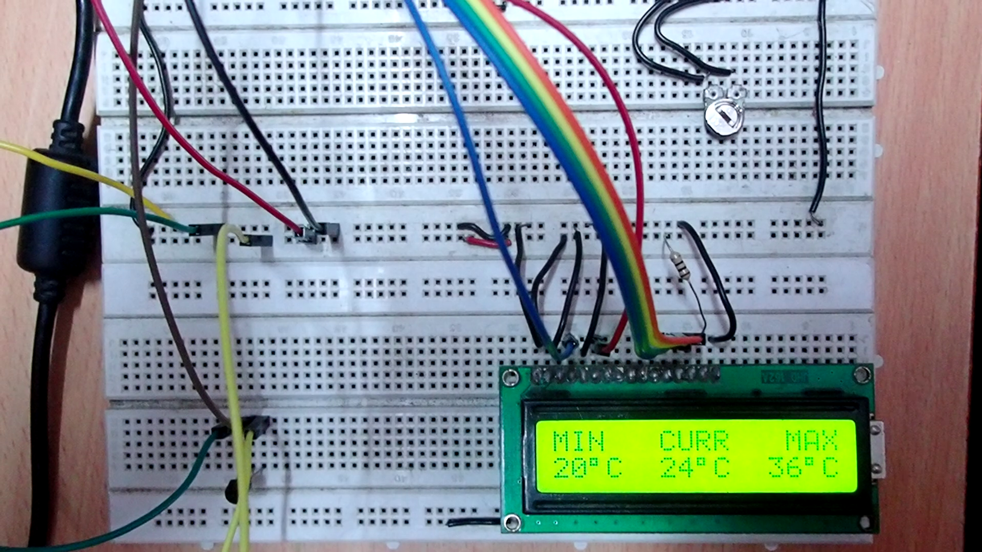
Practical observations
When this Arduino-based, LM35 basic centigrade temperature sensor was put under the test in an AC-ventilated room, it was found that the minimum recorded temperature was 20˚C. Without air conditioning, the maximum temperature of the room was 36˚C (during the summer season). When the air conditioner was set to 22˚C, the recorded temperature was between 24˚ and 25˚C.
[Links to Video P02-DV of this project]
Filed Under: Arduino Projects, Electronic Projects, Sensors, Tutorials, Video
Questions related to this article?
👉Ask and discuss on EDAboard.com and Electro-Tech-Online.com forums.
Tell Us What You Think!!
You must be logged in to post a comment.