In this project, we’ll design a wireless joystick dc motor controller using ATtiny85 and Arduino. It will offer a long range, operating up to 1 km. (You can learn how to control the joystick’s motor speed and direction using Arduino in this article.)
Wireless joystick controls for dc motors are used in many industrial, domestic, and robotic applications. Examples include:
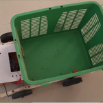
- Shopping carts
- Luggage crane controller
- CCTV camera angle controller
- Pick-and-place robot controller
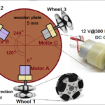
- Omni-directional robot controller
Features that make this project unique:
- There are few components used on the transmitter or receiver side.
- The transmitter uses the ATtiny85 as an MCU, the HC12 (RF trans-receiver) module, and a joystick.
- The receiver uses the Arduino NANO board as an MCU with a motor driver chip and the HC12 module.
- It uses a miniature 8-pin microcontroller (which uses the ATtiny85, a remote-control transmitter).
- The long control and operation range is approximately 1.8 km — thanks to the serial RF transceiver module HC12.
As the joystick moves up-and-down or left-to-right from the transmitter side, it controls the speed and direction of the dc motor on the receiver side. This allows a user to wirelessly control the dc motor from a long-range using the joystick.
System block diagram

Figure 1. The system block diagram with the wireless joystick’s transmitter and receiver. It’s controlled by a dc motor using the ATtin85 and Arduino.
The system consists of two parts: a transmitter and a receiver.
1. The transmitter – a long-range RF remote control with a joystick. It uses a joystick, the ATtiny85 microcontroller, the HC12 RF trans-receiver module, and a 6V battery.
The components include:
- Joystick: a two-axis resistive joystick that generates two analog outputs of 0 – 5V (Vx and Vy) for its movement in the X and Y axes. These two outputs are provided as input to the ATtiny85.
- ATtiny85: a transmitter MCU that receives analog inputs from the joystick. It reads its X and Y movement and sends a specific code that relates to the joystick movement to the HC12.
- HC12: a 434 MHz RF serial trans-receiver module that receives specific code from the ATtiny85 serially and transmits it.
- Battery: a Li-ion type 6-V battery that provides power to all of the blocks.
2. The receiver – a dc motor controller that controls the speed and direction of the motor. It’s build using the Arduino NANO board, a motor driver module, and the HC12 RF trans-receiver module.
The components include:
- HC12: receives code that’s transmitted by the HC12 module and passes it onto the Arduino NANO board and the microcontroller ATMega328 serially.
- Arduino NANO board: receives code serially from the HC12 and controls the direction and speed of the dc motor as per the code. It generates two PWM signals to control the speed of motor in either direction.
- Motor driver module: provides the required voltage (12 V) and current to run the motor.
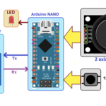
Transmitter circuit diagram

Figure 2. The circuit connections of the transmitter with the ATtiny85, the HC12, and the joystick.
The transmitter circuit is built using five components: a joystick, the ATtiny85, the HC12, an LED, and a battery. The two–axis joystick has four connections: (1) Vcc, (2) Gnd, (3) Vx, and (4) Vy. The Vcc and Gnd pins are connected to the +Ve and -Ve terminals of the battery for biasing. The Vx and Vy pins are connected to pins 2 and 3 of the ATtiny85, which are the chip’s analog inputs.
The HC12 module has four connections: (1) Vcc, (2) Gnd, (3) Tx, and (4) Rx. The Vcc and Gnd pins are connected to the +Ve and -Ve terminals of the battery for biasing. The Tx and Rx pins are connected to the digital I/O pins D1 (pin 6) and D2 (pin 7) of ATtiny85, which will work as serial Rx and Tx of the chip. The LED is connected with the digital I/O pin 5 of ATtiny85.
Receiver circuit diagram
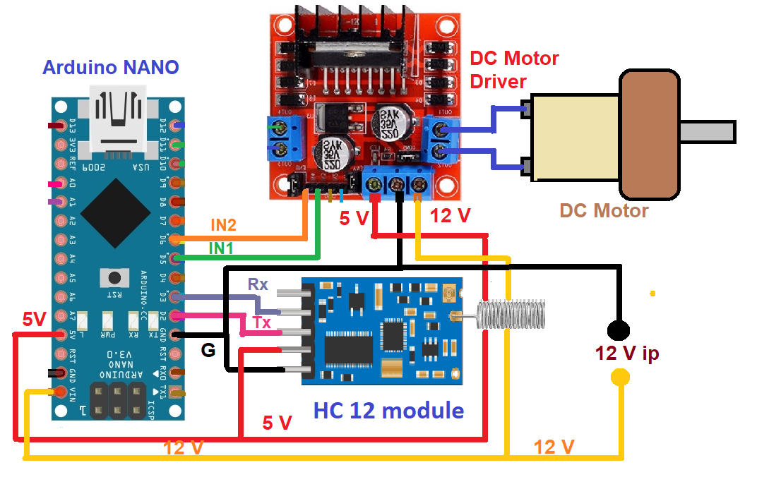
Figure 3. The circuit connections on the receiver side, including Arduino NANO, the dc motor, and the HC12 moduele.
The receiver circuit is built using three modules (components): the Arduino NANO board, an HC12 module, and the dc motor driver module.
The HC12 module is an essential part of the circuit, with four distinct connections: (1) Vcc, (2) Gnd, (3) Tx, and (4) Rx. Connect the Vcc and Gnd pins to 5-V output and connect the Gnd pins of the motor driver module’s 5V supply. Then, connect the Tx and Rx pins to Arduino’s digital I/O pins D2 and D3, which will function as the serial Rx and Tx.
The motor driver module has two motor input connections, IN1 and IN2, which connect with Arduino’s PWM outputs D5 and D6 . The dc motor connects with the module’s Motor 1 outputs, as shown in the abovediagram. An external 12V supply is provided to the module’s 12-V input, and its 5-V output is given to the HC12 module and Arduino.
Working and operation
On the transmitter side:
The joystick
The two-axis joystick has two potentiometers inside; both are connected with 5 V and the ground. As the joystick is moved left-and-right, one of the potentiometer’s resistance varies, generating a variable output of 0 – 5V as Vx.
Similarly, as the joystick is moved up-and-down, the other potentiometer’s resistance varies, generating a variable output of 0 – 5V as Vy. These Vx and Vy outputs are given as analog input to the ATtiny85 microcontroller.
The ATtiny85 microcontroller
The ATtiny85 receives two analog inputs, Vx and Vy, from the joystick. It converts them into equivalent digital values using an inbuilt 10-bit Adc. The analog voltage of 0 – 5 V is converted into a digital value of 0 – 1023. The Vx analog voltage of 0-5 V is converted into digital value X as 0 – 1023, and the Vy analog voltage of 0-5 V is converted into digital value Y as 0 – 1023.
If this digital value is above or below a certain threshold value, ATtiny85 will send a specific code (a command) to the HC12 for transmission. See the table below for reference.

Arduino generates two PWM signals to control the speed and direction of the dc motor.
- When it receives the code ‘F,’ it generates a PWM on pin D5, and the motor rotates forward.
- When it receives the code ‘R,’ it generates a PWM on pin D6, and the motor rotates in reverse.
- When it receives the code ‘I,’ it increases the width of the PWM signal, and the motor speed increases.
- When it receives the code ‘D,’ it decreases the width of the PWM signal, and the motor speed decreases.
The motor driver module receives a 5-V PWM input from the microcontroller and generates a 12-V PWM to drive the 12-V motor. It also provides the motor with the required current for running.
Software program and logic
The program for the ATtiny85 microcontroller transmitter is prepared and compiled in Arduino IDE’s software. It’s written in Arduino C/C++.
Software overview:
- The program reads two analog inputs from ATtiny85 analog input pins A1 and A2 using Arduino’s analogRead () function.
- It communicates with HC12 serially using the SoftwareSerial.h library of Arduino through digital I/O pins D1 and D2.
- The Arduino program uses two libraries on the receiver side, the SoftwareSerial.h and the DC_Motor.h.
- The SoftwareSerial library communicates with the HC12 serially through the digital pins D2 and D3 and the DC_Motor.
- The h library controls DC motor speed and direction.
- The DC_Motor.h library is easy to use and commonly chosen to control dc motor speeds and directions. It has many built-in functions for controlling the operation of dc motors.
The transmitter and receiver programs
Video
You may also like:


Filed Under: Circuit Design
Questions related to this article?
👉Ask and discuss on Electro-Tech-Online.com and EDAboard.com forums.
Tell Us What You Think!!
You must be logged in to post a comment.