
Note: it’s recommended to follow this VHDL tutorial series in order, starting with the first tutorial. Follow the full series here. In the previous Verilog Tutorial – 14, we learned how to design circuits for a 1×8 demultiplexer and an 8×1 multiplexer in Verilog. In this tutorial, we’ll: Write a Verilog program to build a clocked SR latch…
Verilog Tutorial 14: How to design a 1×8 demultiplexer and an 8×1 multiplexer in Verilog
Note: it’s recommended to follow this VHDL tutorial series in order, starting with the first tutorial. Follow the full series here. In the previous Verilog Tutorial – 13, we learned how to design a 3×8 decoder and an 8×3 encoder in VHDL. In this tutorial, we’ll: Write a Verilog program to build circuits for a 1×8 demultiplexer and an…
Verilog Tutorial 13: How to design a 3×8 decoder and an 8×3 encoder in VHDL
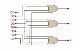
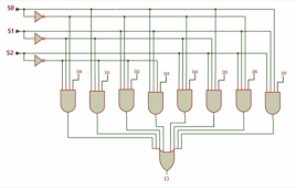
Note: it’s recommended to follow this VHDL tutorial series in order, starting with the first tutorial. Follow the full series here. In the previous Verilog Tutorial – 12, we learned how to design half and full-subtractor circuits in Verilog. In this tutorial, we’ll: Write a Verilog program for building circuits for a 3×8 decoder and an 8×3 encoder…
Verilog Tutorial 12: How to design 8-bit parity generator and checker circuits in Verilog
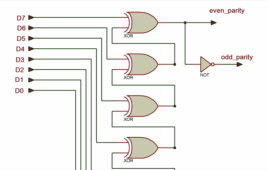
Note: it’s recommended to follow this VHDL tutorial series in order, starting with the first tutorial. Follow the full series here. In the previous Verilog Tutorial – 11, we learned how to design half and full-subtractor circuits in Verilog. In this tutorial, we’ll: Write a Verilog program to build an 8-bit parity generator and checker circuits Verify the…
Verilog Tutorial 11: How to design half and full-subtractor circuits in Verilog
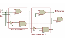
Note: it’s recommended to follow this VHDL tutorial series in order, starting with the first tutorial. Follow the full series here. In the previous Verilog Tutorial – 10, we designed half and full-adder circuits in Verilog. In this tutorial, we’ll: Write a Verilog program that builds half and full-subtractor circuits Verify the output waveform of the program…
Verilog Tutorial 10: How to design half and full-adder circuits in Verilog

Note: it’s recommended to follow this VHDL tutorial series in order, starting with the first tutorial. Follow the full series here. In the previous tutorial, VHDL Tutorial – 9, we learned how to build digital circuits using Boolean equations. In this tutorial, we’ll: Write a Verilog program that builds half and full-adder circuits Verify the output…
Verilog Tutorial 9: How to design a digital circuit for a Boolean equation using Verilog
In the previous Verilog tutorial, we learned how to build various logic gates — such as AND, OR, NOR, and NOT — using only the NOR gates in Verilog. As such, we demonstrated that NOR is a universal gate. (If you haven’t been following this Verilog tutorial series in order, we recommend reviewing the previous…
How to use NOR as the universal gate in Verilog

In the previous Verilog tutorial, we learned how to implement various logic gates, including AND, OR, NOR, and NOT, using only NAND gates in Verilog, demonstrating that NAND is a universal gate. (If you haven’t been following this Verilog tutorial series in order, we recommend reviewing the previous tutorials before proceeding with this one. View…
How to design and verify D’Morgan’s Theorem in Verilog-Part 6

In tutorial 5 of this series, we built NAND, NOR, XOR, and XNOR gates using AND, OR, and NOT gates in Verilog. (If you haven’t been following along, we highly recommend reviewing the previous tutorials before proceeding with this one. The first tutorial starts here.) In this tutorial, we’ll: Write a Verilog program to design…
How to design, simulate, and verify in Verilog using the AND-OR-NOT gates-Part 5
In the previous Verilog tutorial, we designed and simulated all seven basic logic gates (including, AND, OR, NOT, NAND, NOR, XOR, and XNOR) in Verilog. (If you haven’t been following this VHDL tutorial series step by step, it’s recommended to start here, and review the previous tutorials before continuing.) In this tutorial, we’ll: Write a…
How to design, simulate, and verify all digital gates in Verilog-Part 4
In previous Verilog tutorials (especially Tutorial 3), we learned how to design, simulate, and verify digital circuits using Altera’s MAX+II VHDL/Verilog simulator software. (If you haven’t been following this series sequentially, be sure to review the previous tutorials before proceeding.) In this tutorial, we’ll: Write a Verilog program to build various digital logic gates. Simulate…
How to compile, simulate, and verify a Verilog program using MAX+II-Part 3

In the previous two tutorials, we covered the basics of Verilog and explored several example programs using different modeling styles. In this tutorial, we will focus on how to simulate and verify Verilog programs. To edit, compile, execute (simulate), or verify a Verilog program, you will need a software tool like Xilinx’s ISE, Mentor Graphics’…
What is Verilog, its features, and design flow?- Part 2
Verilog is a hardware description language (HDL) first standardized by the Institute of Electrical and Electronics Engineers (IEEE) in 1995. It plays an essential role in electronic design automation (EDA) tools for designing and documenting digital systems. Verilog is extensively used in the design and verification of digital circuits at various abstraction levels, from the…
What are the fundamentals of Verilog programs?-Part 1

In the previous tutorial, we covered the fundamentals of Verilog, VLSI design flow, and various Verilog modeling styles, including modules and data types. Now, it’s time to dive into the Verilog programming. In this tutorial, we’ll present basic Verilog programs for popular digital circuits. Before we begin, it’s worth reviewing the prerequisites for Verilog programming,…
How to setup headless Raspberry Pi for remote access using SSH and VNC

Raspberry Pi is currently the most widely used single-board computer in the world. Launched in October 2023, Raspberry Pi 5 is the latest version of the development board, offering more significant computing power, an enhanced GPU, and faster memory than its predecessors. Among single-board computers, Raspberry Pi remains the most ubiquitous, outpacing alternatives like BeagleBone,…
How to use NAND as a universal gate in Verilog

In tutorial 6 of this series, we built a circuit for D Morgan’s Theorems in Verilog, verifying its output to prove the theorems. (If you haven’t been following along, we highly recommend reviewing the previous tutorials before proceeding with this one. The first tutorial starts here.) In this tutorial, we’ll: Write a Verilog program to…
How to create holiday lights without programming knowledge

The holiday season is just around the corner. Although there’s no shortage of ready-made solutions for lighting up the Christmas tree, creating a personalized set of lights can get you in the holiday spirit. In this article, we’ll explore an easy way to design your own RGB lights for Christmas — without the need for…
How to design a lab power supply at home

The voltage requirements for different circuits vary much like microcontroller-based circuits require 5 V, motor controller or relay driver circuit requires 12 V, and other digital circuits require 3.3 V. If a circuit fails to receive its rated voltage and current, it will not work properly. So, it often makes sense to use a variable…
Best practices for securing LoRa networks

This article explains how to establish secure communication between two LoRa end-node devices using Lora E5 mini boards. LoRa, which stands for “long range,” is a wireless technology with the ability to send small amounts of data over large distances. Two end-node devices can exchange encrypted messages. The transmitting device encrypts the message before sending…
What are the different methods of transistor biasing?

A bipolar junction transistor (BJT) is commonly used as an amplifier or switch in electronic circuits. As a three-terminal device, it has an input stage and an output stage. At the input stage, the VI characteristics of a transistor are similar to the forward-bias characteristics of a signal diode. The transistor turns on (i.e., begins…