Engineers Garage

  • Electronic Projects & Tutorials
    • Electronic Projects
      • Arduino Projects
      • AVR
      • Raspberry pi
      • ESP8266
      • BeagleBone
      • 8051 Microcontroller
      • ARM
      • PIC Microcontroller
      • STM32
    • Tutorials
      • Audio Electronics
      • Battery Management
      • Brainwave
      • Electric Vehicles
      • EMI/EMC/RFI
      • Hardware Filters
      • IoT tutorials
      • Power Tutorials
      • Python
      • Sensors
      • USB
      • VHDL
    • Circuit Design
    • Project Videos
    • Components
  • Articles
    • Tech Articles
    • Insight
    • Invention Stories
    • How to
    • What Is
  • News
    • Electronic Product News
    • Business News
    • Company/Start-up News
    • DIY Reviews
    • Guest Post
  • Forums
    • EDABoard.com
    • Electro-Tech-Online
    • EG Forum Archive
  • DigiKey Store
    • Cables, Wires
    • Connectors, Interconnect
    • Discrete
    • Electromechanical
    • Embedded Computers
    • Enclosures, Hardware, Office
    • Integrated Circuits (ICs)
    • Isolators
    • LED/Optoelectronics
    • Passive
    • Power, Circuit Protection
    • Programmers
    • RF, Wireless
    • Semiconductors
    • Sensors, Transducers
    • Test Products
    • Tools
  • Learn
    • eBooks/Tech Tips
    • Design Guides
    • Learning Center
    • Tech Toolboxes
    • Webinars & Digital Events
  • Resources
    • Digital Issues
    • EE Training Days
    • LEAP Awards
    • Podcasts
    • Webinars / Digital Events
    • White Papers
    • Engineering Diversity & Inclusion
    • DesignFast
  • Guest Post Guidelines
  • Advertise
  • Subscribe

Verilog Tutorial 9: How to design a digital circuit for a Boolean equation using Verilog

By Ashutosh Bhatt March 23, 2025

In the previous Verilog tutorial, we learned how to build various logic gates — such as AND, OR, NOR, and NOT — using only the NOR gates in Verilog. As such, we demonstrated that NOR is a universal gate.

(If you haven’t been following this Verilog tutorial series in order, we recommend reviewing the previous tutorials before proceeding with this one. View the full VHDL tutorial series here.)

In this tutorial, we’ll:

  • Write a Verilog program to construct a digital circuit from a given Boolean equation.
  • Verify the program’s output waveform (digital circuit) against the truth table of the Boolean equation.

First, let’s review the Boolean equation AB + AC’ + BC.

Digital circuit

Truth table

Now, let’s write a Verilog program, compile and simulate it, and obtain the output in the form of a waveform. Afterward, we’ll verify that the output waveforms match the given truth table.

(Please follow the step-by-step procedure outlined in Verilog Tutorial 3 to create a project, edit and compile the program, create a waveform file, simulate the program, and generate output waveforms.)

Verilog program

Gate-level modeling:

module bol_equ(a,b,c,y);
  input a,b,c;
  wire t1,t2,t3,c_not;
  output y;
    and(t1, a, b);
    and (t2, b, c);
    not (c_not, c);
    and (t3, a, c_not);
    or(y, t1, t2, t3);
 endmodule

Dataflow modeling:

module bol_equ(a,b,c,y);
input a,b,c;
wire t1,t2,t3;
output y;
  assign t1 = a & b;
  assign t2 = a & ~c;
  assign t3 = b & c;
  assign y = t1 | t2 | t3;
endmodule

Next, compile the above program, creating a waveform file with all of the necessary inputs and outputs that are listed, and simulate the project.

Simulation waveform

You can verify the output “y” by comparing it with the given truth table. It should be observed that the output matches the truth table.

Now, let’s consider another Boolean equation: A + B’C + A’C + BC’

Digital circuit

Truth table

Verilog program

Gate-level modeling:

module boolean_equ (a, b, c, y)
 input a, b, c;
 output y;
 wire t1, t2, t3, t4, t5, a_not, b_not, c_not;
not(a_not, a);
not(b_not, b);
not(c_not, c);
and(t1, b_not, c);
or(t4, a, t1);
and(t2, a_not, c);
and(t3, b, c_not);
or(t5, t2, t3);
or(y, t4, t5);
endmodule

Dataflow modeling:

module boolean_equ (a, b, c, y)
 input a, b, c;
 output y;
   wire t1, t2, t3, t4, t5;
    assign t1 = (~b & c);
           assign t2 = (~a & c);
    assign t3 = (b & ~c);
    assign t4 = (a | t1);
    assign t5 = (t2 | t3);
    assign y = (t4 | t5);
  endmodule

Next, compile the above program, creating a waveform file with all of the necessary inputs and outputs that are listed, and simulate the project.

Simulation waveform

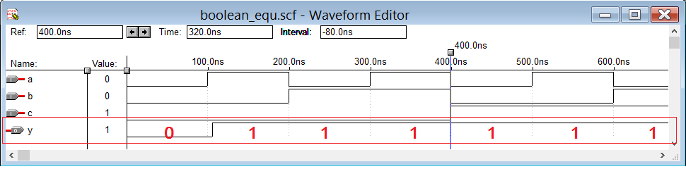
You can verify that the output “y” is always “1” for all input conditions of a, b, and c — except when all three inputs are “0.”

As a result, using Verilog, we can design a digital circuit for any given Boolean equation.

In the next tutorial, we will learn how to design half-adder and full-adder circuits using Verilog.


You may also like:


  • How to use NOR as the universal gate in Verilog

  • How to design and verify D’Morgan’s Theorem in Verilog-Part 6

  • How to design, simulate, and verify in Verilog using the…

  • How to design, simulate, and verify all digital gates in…

  • How to compile, simulate, and verify a Verilog program using…

  • What is Verilog, its features, and design flow?- Part 2

  • What are the fundamentals of Verilog programs?-Part 1

  • How to use NAND as a universal gate in Verilog

Filed Under: Tutorials
Tagged With: boolean, booleanequation, circuits, digitalcircuits, simulationwaveform, tutorial, verilog
 

Next Article

← Previous Article
Next Article →

Questions related to this article?
👉Ask and discuss on Electro-Tech-Online.com and EDAboard.com forums.


Tell Us What You Think!! Cancel reply

You must be logged in to post a comment.

EE TECH TOOLBOX

“ee
Tech Toolbox: Internet of Things
Explore practical strategies for minimizing attack surfaces, managing memory efficiently, and securing firmware. Download now to ensure your IoT implementations remain secure, efficient, and future-ready.

EE Learning Center

EE Learning Center
“engineers
EXPAND YOUR KNOWLEDGE AND STAY CONNECTED
Get the latest info on technologies, tools and strategies for EE professionals.

HAVE A QUESTION?

Have a technical question about an article or other engineering questions? Check out our engineering forums EDABoard.com and Electro-Tech-Online.com where you can get those questions asked and answered by your peers!


RSS EDABOARD.com Discussions

  • Reducing "shoot-through" in offline Full Bridge SMPS?
  • High Side current sensing
  • How to simulate power electronics converter in PSpice?
  • Voltage mode pushpull is a nonsense SMPS?
  • Layout IRN reduction in Comparator

RSS Electro-Tech-Online.com Discussions

  • Back to the old BASIC days
  • Parts required for a personal project
  • PIC KIT 3 not able to program dsPIC
  • Failure of polypropylene motor-run capacitors
  • Siemens large industrial PLC parts

Featured – RPi Python Programming (27 Part)

  • RPi Python Programming 21: The SIM900A AT commands
  • RPi Python Programming 22: Calls & SMS using a SIM900A GSM-GPRS modem
  • RPi Python Programming 23: Interfacing a NEO-6MV2 GPS module with Raspberry Pi
  • RPi Python Programming 24: I2C explained
  • RPi Python Programming 25 – Synchronous serial communication in Raspberry Pi using I2C protocol
  • RPi Python Programming 26 – Interfacing ADXL345 accelerometer sensor with Raspberry Pi

Recent Articles

  • What is AWS IoT Core and when should you use it?
  • AC-DC power supply extends voltage range to 800 V DC
  • Infineon’s inductive sensor integrates coil system driver, signal conditioning circuits and DSP
  • Arm Cortex-M23 MCU delivers 87.5 µA/MHz active mode
  • STMicroelectronics releases automotive amplifiers with in-play open-load detection

EE ENGINEERING TRAINING DAYS

engineering

Submit a Guest Post

submit a guest post
Engineers Garage
  • Analog IC TIps
  • Connector Tips
  • Battery Power Tips
  • DesignFast
  • EDABoard Forums
  • EE World Online
  • Electro-Tech-Online Forums
  • EV Engineering
  • Microcontroller Tips
  • Power Electronic Tips
  • Sensor Tips
  • Test and Measurement Tips
  • 5G Technology World
  • Subscribe to our newsletter
  • About Us
  • Contact Us
  • Advertise

Copyright © 2025 WTWH Media LLC. All Rights Reserved. The material on this site may not be reproduced, distributed, transmitted, cached or otherwise used, except with the prior written permission of WTWH Media
Privacy Policy

Search Engineers Garage

  • Electronic Projects & Tutorials
    • Electronic Projects
      • Arduino Projects
      • AVR
      • Raspberry pi
      • ESP8266
      • BeagleBone
      • 8051 Microcontroller
      • ARM
      • PIC Microcontroller
      • STM32
    • Tutorials
      • Audio Electronics
      • Battery Management
      • Brainwave
      • Electric Vehicles
      • EMI/EMC/RFI
      • Hardware Filters
      • IoT tutorials
      • Power Tutorials
      • Python
      • Sensors
      • USB
      • VHDL
    • Circuit Design
    • Project Videos
    • Components
  • Articles
    • Tech Articles
    • Insight
    • Invention Stories
    • How to
    • What Is
  • News
    • Electronic Product News
    • Business News
    • Company/Start-up News
    • DIY Reviews
    • Guest Post
  • Forums
    • EDABoard.com
    • Electro-Tech-Online
    • EG Forum Archive
  • DigiKey Store
    • Cables, Wires
    • Connectors, Interconnect
    • Discrete
    • Electromechanical
    • Embedded Computers
    • Enclosures, Hardware, Office
    • Integrated Circuits (ICs)
    • Isolators
    • LED/Optoelectronics
    • Passive
    • Power, Circuit Protection
    • Programmers
    • RF, Wireless
    • Semiconductors
    • Sensors, Transducers
    • Test Products
    • Tools
  • Learn
    • eBooks/Tech Tips
    • Design Guides
    • Learning Center
    • Tech Toolboxes
    • Webinars & Digital Events
  • Resources
    • Digital Issues
    • EE Training Days
    • LEAP Awards
    • Podcasts
    • Webinars / Digital Events
    • White Papers
    • Engineering Diversity & Inclusion
    • DesignFast
  • Guest Post Guidelines
  • Advertise
  • Subscribe