Engineers Garage

  • Electronic Projects & Tutorials
    • Electronic Projects
      • Arduino Projects
      • AVR
      • Raspberry pi
      • ESP8266
      • BeagleBone
      • 8051 Microcontroller
      • ARM
      • PIC Microcontroller
      • STM32
    • Tutorials
      • Audio Electronics
      • Battery Management
      • Brainwave
      • Electric Vehicles
      • EMI/EMC/RFI
      • Hardware Filters
      • IoT tutorials
      • Power Tutorials
      • Python
      • Sensors
      • USB
      • VHDL
    • Circuit Design
    • Project Videos
    • Components
  • Articles
    • Tech Articles
    • Insight
    • Invention Stories
    • How to
    • What Is
  • News
    • Electronic Product News
    • Business News
    • Company/Start-up News
    • DIY Reviews
    • Guest Post
  • Forums
    • EDABoard.com
    • Electro-Tech-Online
    • EG Forum Archive
  • DigiKey Store
    • Cables, Wires
    • Connectors, Interconnect
    • Discrete
    • Electromechanical
    • Embedded Computers
    • Enclosures, Hardware, Office
    • Integrated Circuits (ICs)
    • Isolators
    • LED/Optoelectronics
    • Passive
    • Power, Circuit Protection
    • Programmers
    • RF, Wireless
    • Semiconductors
    • Sensors, Transducers
    • Test Products
    • Tools
  • Learn
    • eBooks/Tech Tips
    • Design Guides
    • Learning Center
    • Tech Toolboxes
    • Webinars & Digital Events
  • Resources
    • Digital Issues
    • EE Training Days
    • LEAP Awards
    • Podcasts
    • Webinars / Digital Events
    • White Papers
    • Engineering Diversity & Inclusion
    • DesignFast
  • Guest Post Guidelines
  • Advertise
  • Subscribe

How to design and verify D’Morgan’s Theorem in Verilog-Part 6

By Michelle Froese March 17, 2025

In tutorial 5 of this series, we built NAND, NOR, XOR, and XNOR gates using AND, OR, and NOT gates in Verilog. (If you haven’t been following along, we highly recommend reviewing the previous tutorials before proceeding with this one. The first tutorial starts here.)

In this tutorial, we’ll:

  • Write a Verilog program to design a digital circuit demonstrating De Morgan’s Theorems.
  • Verify the program’s output waveform (digital circuit) against the truth table for De Morgan’s Theorems.

Statements of De Morgan’s Theorems

Theorem 1. The complement of the sum of two or more variables is equal to the product of the complements of the variables. This means:

Theorem 2. The complement of the product of two or more variables is equal to the sum of the complement of the variables. This means:

Let’s begin with the digital circuit for which we’ll write the Verilog program.

Digital circuit

Here are the truth tables for the above circuit.

Next, let’s write the Verilog program, compile and simulate it, and generate the output as a waveform. Then, we’ll verify the output waveforms against the given truth table.

(Please refer to the step-by-step procedure in Verilog Tutorial 3 to create a project, edit and compile the program, create a waveform file, simulate the program, and generate output waveforms.)

Verilog program

Gate level modeling:

module d_morgan(a,b, or_not_op,not_and_op,and_not_op, not_or_op);
  input a,b;
  output or_not_op,not_and_op,and_not_op, not_or_op;
  wire a_bar,b_bar;
     not(a_bar,a);
     not(b_bar,b);
     nand(and_not_op,a,b);
     or(not_or_op,a_bar,b_bar);
     nor(or_not_op,a,b);
     and(not_and_op,a_bar,b_bar);
endmodule

Dataflow modeling:

module d_morgan(a,b,or_not_op,not_and_op,and_not_op, not_or_op);
  input a,b;
  output or_not_op,not_and_op,and_not_op, not_or_op;
     assign and_not_op = ~(a & b);
     assign not_or_op = ~a | ~b;
     assign or_not_op = ~(a | b);
     assign not_and_op = ~a & ~b;
endmodule

Behavior modeling:

module d_morgan(a,b, or_not_op,not_and_op,and_not_op, not_or_op);
  input a,b;
  output or_not_op,not_and_op,and_not_op, not_or_op;
  always @(a, b)
   begin

      and_not_op = ~(a & b);
      not_or_op = ~a | ~b;

      or_not_op = ~(a | b);
      not_and_op = ~a & ~b;
   end
 endmodule

(To learn more about Verilog programs, be sure to review Verilog tutorial 1 and Verilog tutorial 2 of these series.)

Now, compile the above program by creating a waveform file with all of the inputs and outputs listed. Then, simulate the project, and you should get the following result.
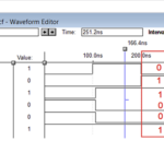
Simulation waveform

Note, you can write the program using one modeling style at a time and then compile it. Afterward, modify the program to use a different modeling style and compile it again.

From the output waveforms, we can observe that the result of OR followed by NOT is the same as NOT followed by AND. This is highlighted in the figure. Similarly, the other two outputs are also identical.

This confirms the validity of De Morgan’s theorems.

In the next tutorial, we’ll demonstrate how a NAND gate can function as a universal gate by designing AND, OR, NOT, XOR, and XNOR gates using only NAND gates.


~

You may also like:


  • How to design, simulate, and verify in Verilog using the…

  • How to design, simulate, and verify all digital gates in…

  • How to compile, simulate, and verify a Verilog program using…

  • What is Verilog, its features, and design flow?- Part 2

  • What are the fundamentals of Verilog programs?-Part 1

  • How to design a digital circuit using VHDL

Filed Under: Tutorials
Tagged With: dmorganstheorem, tutorial, verilog
 

Next Article

← Previous Article
Next Article →

Questions related to this article?
👉Ask and discuss on EDAboard.com and Electro-Tech-Online.com forums.


Tell Us What You Think!! Cancel reply

You must be logged in to post a comment.

EE TECH TOOLBOX

“ee
Tech Toolbox: Internet of Things
Explore practical strategies for minimizing attack surfaces, managing memory efficiently, and securing firmware. Download now to ensure your IoT implementations remain secure, efficient, and future-ready.

EE Learning Center

EE Learning Center
“engineers
EXPAND YOUR KNOWLEDGE AND STAY CONNECTED
Get the latest info on technologies, tools and strategies for EE professionals.

HAVE A QUESTION?

Have a technical question about an article or other engineering questions? Check out our engineering forums EDABoard.com and Electro-Tech-Online.com where you can get those questions asked and answered by your peers!


RSS EDABOARD.com Discussions

  • Reducing "shoot-through" in offline Full Bridge SMPS?
  • High Side current sensing
  • How to simulate power electronics converter in PSpice?
  • Voltage mode pushpull is a nonsense SMPS?
  • Layout IRN reduction in Comparator

RSS Electro-Tech-Online.com Discussions

  • Back to the old BASIC days
  • Parts required for a personal project
  • PIC KIT 3 not able to program dsPIC
  • Failure of polypropylene motor-run capacitors
  • Siemens large industrial PLC parts

Featured – RPi Python Programming (27 Part)

  • RPi Python Programming 21: The SIM900A AT commands
  • RPi Python Programming 22: Calls & SMS using a SIM900A GSM-GPRS modem
  • RPi Python Programming 23: Interfacing a NEO-6MV2 GPS module with Raspberry Pi
  • RPi Python Programming 24: I2C explained
  • RPi Python Programming 25 – Synchronous serial communication in Raspberry Pi using I2C protocol
  • RPi Python Programming 26 – Interfacing ADXL345 accelerometer sensor with Raspberry Pi

Recent Articles

  • What is AWS IoT Core and when should you use it?
  • AC-DC power supply extends voltage range to 800 V DC
  • Infineon’s inductive sensor integrates coil system driver, signal conditioning circuits and DSP
  • Arm Cortex-M23 MCU delivers 87.5 µA/MHz active mode
  • STMicroelectronics releases automotive amplifiers with in-play open-load detection

EE ENGINEERING TRAINING DAYS

engineering

Submit a Guest Post

submit a guest post
Engineers Garage
  • Analog IC TIps
  • Connector Tips
  • Battery Power Tips
  • DesignFast
  • EDABoard Forums
  • EE World Online
  • Electro-Tech-Online Forums
  • EV Engineering
  • Microcontroller Tips
  • Power Electronic Tips
  • Sensor Tips
  • Test and Measurement Tips
  • 5G Technology World
  • Subscribe to our newsletter
  • About Us
  • Contact Us
  • Advertise

Copyright © 2025 WTWH Media LLC. All Rights Reserved. The material on this site may not be reproduced, distributed, transmitted, cached or otherwise used, except with the prior written permission of WTWH Media
Privacy Policy

Search Engineers Garage

  • Electronic Projects & Tutorials
    • Electronic Projects
      • Arduino Projects
      • AVR
      • Raspberry pi
      • ESP8266
      • BeagleBone
      • 8051 Microcontroller
      • ARM
      • PIC Microcontroller
      • STM32
    • Tutorials
      • Audio Electronics
      • Battery Management
      • Brainwave
      • Electric Vehicles
      • EMI/EMC/RFI
      • Hardware Filters
      • IoT tutorials
      • Power Tutorials
      • Python
      • Sensors
      • USB
      • VHDL
    • Circuit Design
    • Project Videos
    • Components
  • Articles
    • Tech Articles
    • Insight
    • Invention Stories
    • How to
    • What Is
  • News
    • Electronic Product News
    • Business News
    • Company/Start-up News
    • DIY Reviews
    • Guest Post
  • Forums
    • EDABoard.com
    • Electro-Tech-Online
    • EG Forum Archive
  • DigiKey Store
    • Cables, Wires
    • Connectors, Interconnect
    • Discrete
    • Electromechanical
    • Embedded Computers
    • Enclosures, Hardware, Office
    • Integrated Circuits (ICs)
    • Isolators
    • LED/Optoelectronics
    • Passive
    • Power, Circuit Protection
    • Programmers
    • RF, Wireless
    • Semiconductors
    • Sensors, Transducers
    • Test Products
    • Tools
  • Learn
    • eBooks/Tech Tips
    • Design Guides
    • Learning Center
    • Tech Toolboxes
    • Webinars & Digital Events
  • Resources
    • Digital Issues
    • EE Training Days
    • LEAP Awards
    • Podcasts
    • Webinars / Digital Events
    • White Papers
    • Engineering Diversity & Inclusion
    • DesignFast
  • Guest Post Guidelines
  • Advertise
  • Subscribe