In the previous tutorial, we discussed synchronous serial communication in Raspberry Pi using I2C protocol. In this tutorial, we will use the I2C interface of Raspberry Pi to communicate with a digital sensor. The digital sensor that we will talk with is the ADXL345 accelerometer. ADXL345 is a small, ultra-low power, 3-axis accelerometer sensor that is used in electronic control systems of mobile device applications like mobile handsets, smartphones, gaming devices, pointing devices, personal navigation devices, hard drive protection, medical and industrial instrumentation.
ADXL345 accelerometer
ADXL345 is a 3-axis MEMS capacitive digital accelerometer sensor. It has a user-selectable range up to +/-16g, a maximum output resolution of 13 bits, sensitivity of 3.9 mg/LSB, and a maximum output data rate of 3200 Hz. It is a digital sensor in a 14-lead package that outputs sensor data through I2C and SPI interfaces. ADXL345 measures static acceleration due to gravity as well as dynamic acceleration resulting from motion or shock. It can be used to sense linear acceleration in 3 axes, tilt and free fall of an object. The sensor also has two interrupt pins and supports built-in sensing functions like free-fall detection and tapping by mapping sensing functions to its interrupt pins. ADXL345 can detect the presence or lack of motion by comparing acceleration values to user-defined thresholds.
The most basic thing that is done with any accelerometer sensor is getting the acceleration values. The ADXL345 sensor is a digital sensor, so it has several built-in registers that can be read and written over I2C or SPI. By reading and writing data to these registers, a controller/computer can configure the sensor (like set different measurement range, data transfer rate, sensitivity, and resolution), read acceleration values, set thresholds, map interrupts, and use built-in sensing functions.
ADXL345 offers four measurement range: +/-2g, +/-4g, +/-8g, and +/-16g. The default measurement range is +/-2g, which can be used to sense acceleration up to 19.6 m/s2 in either direction along each axis. The available resolutions are 10-bit for +/-2g, 11-bit for +/-4g, 12-bit for +/-8g and 13-bit for +/-16g range. The default resolution is 10-bit, which for +/-2g (default) range allows sensitivity of 3.9mg/LSB. The default data rate is 100 Hz. All these configurations can be changed or set by writing data to built-in registers of ADXL345. A controller/computer can read acceleration by reading values from registers 0x32 to 0x37. Learn more about the ADXL345 accelerometer sensor, its various technical specifications, and its practical implications.
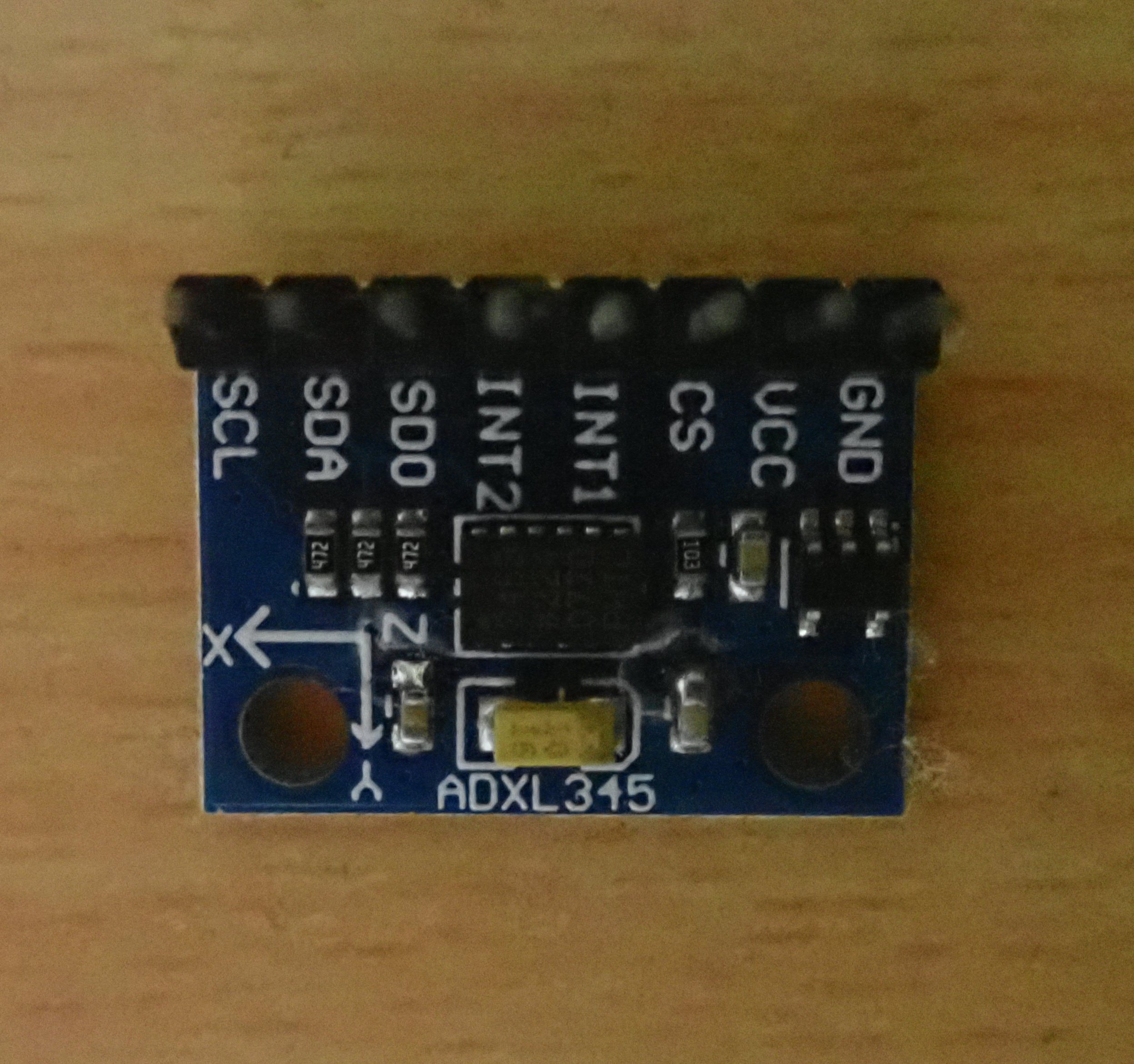
Example of ADXL345 accelerometer sensor module.
Interfacing ADXL345 with Raspberry Pi
Interfacing the ADXL345 sensor with Raspberry Pi is pretty straightforward. The digital sensor communicates data over I2C and SPI interfaces. In any ADXL345 sensor module, pins for both interfaces (I2C/TWI and SPI) and interrupt pins are available. The sensor supports both 3-wire and 4-wire SPI. Raspberry Pi has both I2C and SPI interfaces, and either can be used to talk with ADXL345.
In this tutorial, we are using I2C to talk with ADXL345. The user I2C of Raspberry Pi is available at pins GPIO2 (Board Pin No. 3) and GPIO3 (Board Pin No. 5). GPIO2 is Serial Data (SDA) line, and GPIO3 is a Serial Clock (SCL) line of the I2C1. These I2C pins are internally pulled up to 3.3V via 1.8 k ohms resistors. So, the I2C lines of ADXL345 can be directly connected to the user’s I2C port of Raspberry Pi without the need for any external circuitry.
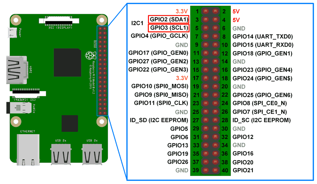
I2C interface on Raspberry Pi’s GPIO header.
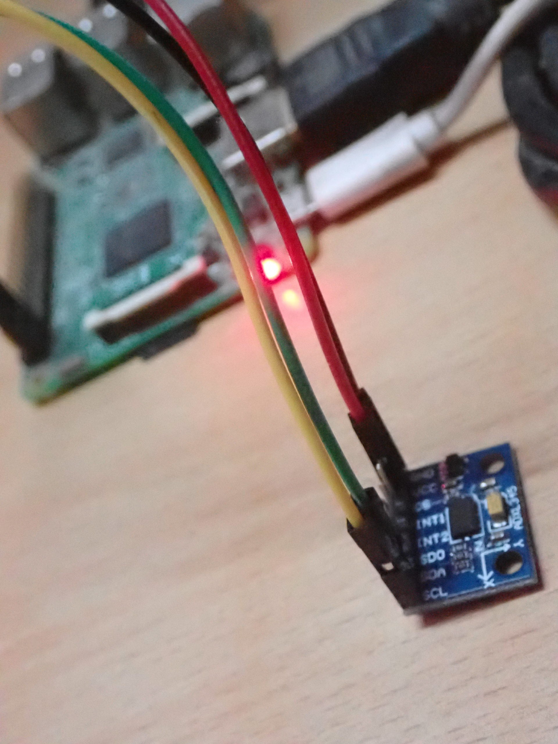
ADXL345 requires an operating voltage of 2.5V that can range from 2.0V to 3.6V. It consumes approximately 30 uA for a data transfer rate of less than 10 Hz and around 140 uA for data transfer rates above 100 Hz. The ADXL345 sensor can be supplied 3.3V supply with common ground from the Raspberry Pi itself, while the I2C channels can be directly connected without the need for any external pull-up circuit.
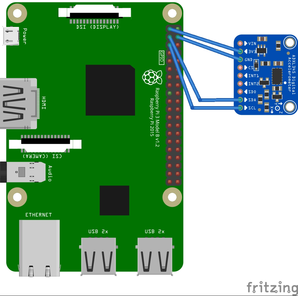
Circuit diagram for interfacing ADXL345 with Raspberry Pi.
I2C communication in Raspberry Pi
Raspberry Pi has two I2C ports, I2C0 and I2C1. The I2C1 is available for users, while I2C0 remains reserved for reading EEPROM of Raspberry Pi’s add-on boards called Hardware on The Top (HAT) boards. In older versions (256 MB) of Raspberry Pi, I2C0 was available for users and I2C1 was reserved for HAT boards. The ports were inversed from 512 MB versions of Raspberry Pi.
The I2C ports are connected to built-in Broadcom Serial Controllers (BSC) of Raspberry Pi that support standard-mode I2C-compatible serial communication with data speed up to 400 Kbps. The user I2C1 is disabled by default. It needs to be enabled through Raspberry Pi configurations. Once enabled, the user I2C port is listed as one of the available Linux devices in Raspberry Pi.
On Raspberry Pi, the I2C bus can be accessed in a Python script using the SMBus library. SMBus is a subset of the I2C interface. The Python library for SMBus can be used to communicate with I2C based devices. The latest version of this library is SMbus2. For serial I2C communication with devices like ADXL345, SMBus() method of the library can be used to configure I2C port on Raspberry Pi; read_byte(), read_byte_data() and read_block_data() methods can be used to read data from I2C device; write_byte(), write_byte_data(), and write_block_data() methods can be used to write data to I2C device. Learn more about the I2C protocol and Raspberry Pi’s I2C interface.
Talking with ADXL345 using Raspberry Pi
The I2C1 port of Raspberry Pi can communicate with data speeds up to 400 kbps. The ADXL345 sensor has a maximum output data rate of 3200 Hz or 3.2 kbps. So, the sensor can easily communicate with Raspberry Pi. The output data rate of ADXL345 can be set by writing to BW_RATE (0x2C) register. The I2C voltage levels of both Raspberry Pi and ADXL345 are 3.3V compatible, so there is no need for any logic level shifter between Raspberry Pi and ADXL345. The SDA and SCL lines of both can be directly connected.
ADXL345 has an ALT address pin that can be hardwired to set the I2C address of this digital sensor. If the ALT ADDRESS pin is pulled high in a module, the 7-bit I2C address for the device is 0x1D, followed by the R/W bit. This translates to 0x3A for a write and 0x3B for a read. If the ALT ADDRESS pin is connected to ground, the 7-bit I2C address for the device is 0x53 (followed by the R/W bit). This translates to 0xA6 for a write and 0xA7 for a read.
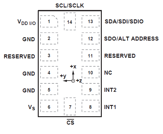
Pin Diagram of ADXL345 accelerometer sensor.
In a module, the ALT ADDRESS pin is already pulled high or low. The I2C address of the ADXL345 sensor can, therefore, be found by scanning for available I2C devices on Raspberry Pi on connecting the sensor. A scan for I2C devices can be conducted on Raspberry Pi using i2c-tools. First of all, install the i2c-tools by running the following command in the Raspberry Pi Terminal:
sudo apt-get install -y i2c-tools
Now run the following command to scan connected I2C slaves:
sudo i2cdetect -y 1
The i2c-detect is a tool that scans the I2C user port and returns the I2C addresses of the connected slave devices. The tool returns a table of addresses of connected I2C slave devices, as shown in the image below:
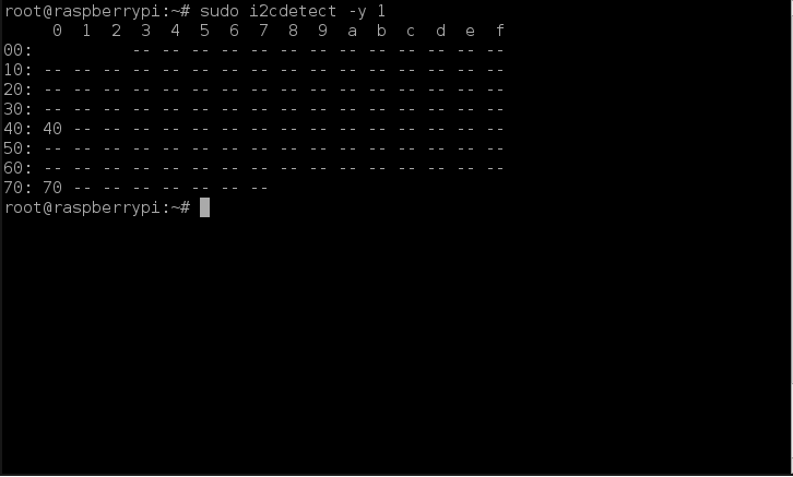
On connecting ADXL345, the i2c-tools must return a table containing either 0x53 or 0x1D as the I2C address. After verifying the I2C address of the ADXL345, I2C port 1 of Raspberry Pi can be used to talk with ADXL345.
The ADXL345 has 8-bit built-in registers. Most of these registers can be read/write while some are read-only. A table of these registers is given below:
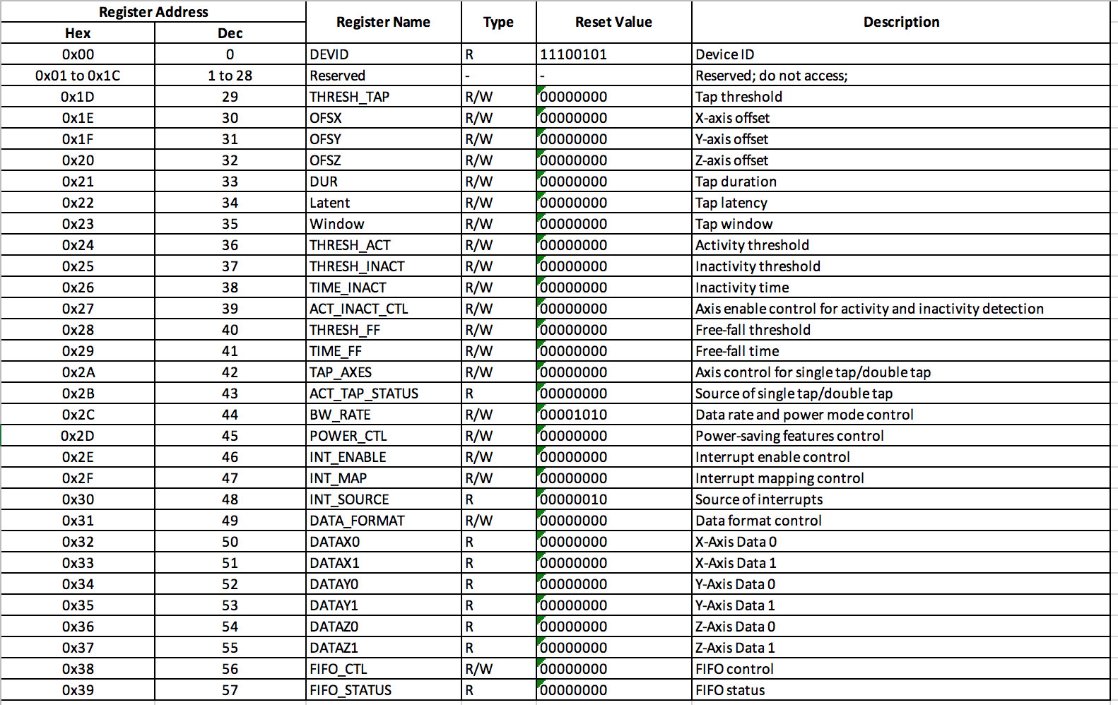
(click to enlarge)
Configuring ADXL345 sensor
Below are listed a few simple steps to configure the ADXL345 sensor for serial communication.
- Set power mode and data transfer rate by writing to the 0x2C register. This register has the following bits:
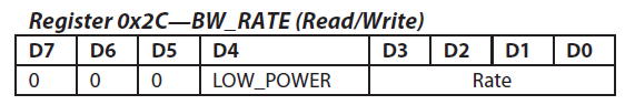
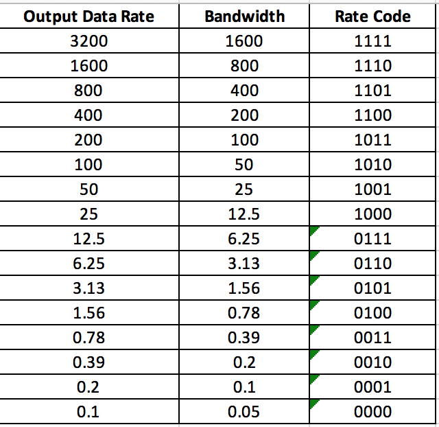
If LOW_POWER bit is set to 0, the ADXL345 works in normal mode, and if it is set to 1, ADXL345 works are reduced power modes, in which there is higher noise. The bits D3 to D0 selects the data transfer rate according to the following table:
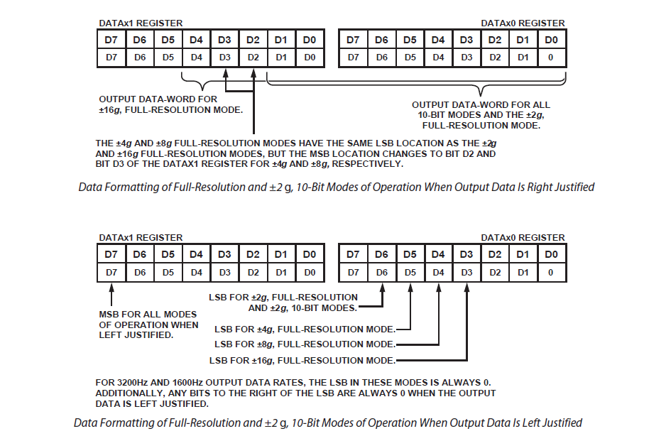
2. Set the data format by writing to 0x31 register. This register has the following bits: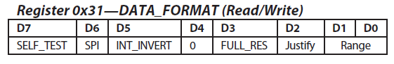 If the SELF-TEST bit is set to 1, a self-test force is applied to the sensor, causing a shift in the output data. If it is set to 0, the self-test force is disabled. If the SPI bit is set to 1, ADXL345 uses 3-wire SPI mode; otherwise, if set to 0, it uses 4-wire SPI mode. If INT_INVERT bit is set to 0, it sets the interrupts to active high, and if it is set to 1, it sets the interrupts to active low. If FULL_RES bit is set to 1, the sensor outputs full-resolution value (10-bit for +/- 2g; 11-bit for +/-4g; 12-bit for +/- 8g; 13-bit for +/- 16g) otherwise if it is set to 0, default 10-bit is used. If the justify bit is set to 1, acceleration values in registers 0x32 to 0x37 are left-justified; otherwise, if it is set to 0, values are right-justified. The following image shows the data format of data-value registers with left and right justification and position of LSB or MSB accordingly for different measurement range.
 The range bits D1 and D0 selects the measurement range according to the following table
- Set power saving features by writing to 0x2D register. This register has the following bits:
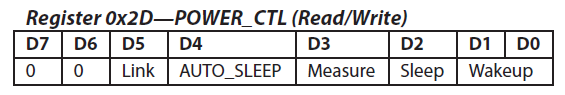
If the link bit is set to 1, activity and inactivity functions are serially linked (activity function is delayed until inactivity function is detected); otherwise, if it is set to 0, both functions are concurrent. The inactivity function refers to a situation when acceleration is below the THRESH_INACT value (0x25 register) for at least the time indicated by TIME_INACT (0x26 register).
If the link bit is set and the AUTO_SLEEP bit is set to 1, it enables the auto-sleep functionality. In this mode, the ADXL345 automatically switches to sleep mode if the inactivity function is enabled and inactivity is detected. If activity is also enabled, the ADXL345 automatically wakes up from sleep after detecting activity and returns to operation at the output data rate set in the BW_RATE register. If the AUTO_SLEEP bit is set to 0, it disables automatic switching to sleep mode. If the link bit is not set, the AUTO_SLEEP feature is disabled, and setting the AUTO_SLEEP bit does not have an impact on device operation.
If Measure bit is set to 1, ADXL345 operates in measurement mode; otherwise, if it is set to 0, ADXL345 operates in standby mode. If Sleep bit is set to 1, ADXL345 operates in sleep mode; otherwise, if it is set to 0, ADXL345 operates in normal mode. Sleep mode suppresses DATA_READY, stops transmission of data to FIFO, and switches the sampling rate to one specified by the wake-up bits. In sleep mode, only the activity function can be used. The wake-up bits control the frequency of reading in sleep mode according to the following table: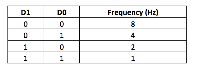
Reading acceleration values from ADXL345
The acceleration along the x-axis is read from registers 0x32 and 0x33; acceleration along Y-axis is read from registers 0x34 and 0x35, and acceleration along Z-axis is read from registers 0x36 and 0x37. The raw values are 16-bit in two’s complement form. The resolution left or right justification of the values and measurement range is set as per the value written to the 0x31 register of ADXL345. Accordingly, the 16-bit values must be masked in a user program.
Once the raw 10-bit/11-bit/12-bit/13-bit acceleration values are derived, the acceleration in the gravity unit can be calculated by multiplying the raw values to 4 mg i.e., by multiplying to 0.004. This way, we get the value of acceleration along X-, Y- and Z- axes in G. These values can be multiplied by 9.8 to convert the acceleration in gravity unit to acceleration in m/s2 (SI units).
It should be noted that the acceleration read by ADXL345 includes both static acceleration (due to gravity of Earth) as well as dynamic acceleration (due to motion or shock). If the sensor has to be used to detect the motion of an object ignoring static acceleration, appropriate offset values must be set in registers 0x1E to 0x20.
The ADXL345 has built-in activity, inactivity, tapping, and free-fall detection sensing functions. These built-in functions can be enabled by setting 0x2E register and mapped to interrupt pins by setting 0x2F registers. These built-in sensing functions of ADXL345 are provided to reduce overload on interfaced controller/computer and are useful in electronic control applications.
Configuring ADXL345 to +/- 2g, 10-bit resolution and reading acceleration using Python
Hopefully, you must have an interfaced ADXL345 accelerometer with Raspberry Pi by now and found out if its I2C address is 0x53 or 0x1D. The ADXL345 sensor used in this tutorial has an I2C address of 0x53. The following Python script configures the ADXL345 sensor to +/- 2g measurement range and uses a 10-bit resolution. The script reads acceleration data of all axes, converts it to gravity units, and finally convert it to SI units.
The script imports the SMBus library for serial I2C communication with ADXL345, time and sleep libraries for providing time delays, and sys library to control script termination. The smbus() method is used to configure the script to communicate over I2C port 1.
First of all, data (0x0B) is written to 0x2C register of ADXL345 over I2C address 0x53 to configure the ADXL345 to use a data output rate of 200 bps. The data is written using bus.write_byte_data() method of the SMbus library. Then, the current status of 0x31 register of ADXL345 (that is at I2C address 0x53) is read using bus.read_byte_data() method. The read value is masked and written back to the 0x31 register of ADXL345 to use the right justification, default 10-bit resolution, and +/- 2g measurement range. The 0x2D register of ADXL345 is set to 0x08 to configure the sensor to operate in measurement mode.
A user-defined function getAxes() is defined that reads acceleration values, return and print them on the console. The function body uses bus.read_i2c_block_data() method to read data from 0x32 to 0x37 registers of ADXL345. The read bytes are stored in variables that are defined to store acceleration values in x, y, and z axes. The two’s complement is removed by bit-masking and bit-shifting the values. The derived raw values are converted to gravity unit by multiplying by 0.004 as the sensor has a sensitivity of 4mg/LSB. The values in the gravity unit are converted to the SI unit by multiplying by 9.80665. Finally, the rounded values of acceleration along x, y, and z axes are printed to the console and returned by the function.
The getAxes() function is called in a try-except statement where the function is called infinitely at a delay of 2 seconds until the Python script detects a keyboard interrupt. On detecting a keyboard interrupt, the script is terminated using sys.exit() function.
Results
Reading raw sensor data from ADXL345
Reading acceleration in SI units from ADXL345:
In the next tutorial, we will discuss the basics of the SPI protocol.
Filed Under: Featured Contributions, Raspberry pi
Questions related to this article?
👉Ask and discuss on Electro-Tech-Online.com and EDAboard.com forums.
Tell Us What You Think!!
You must be logged in to post a comment.