In almost all the microcontroller codes the peripheral initialization functions like uart initialization, spi initialization are written along with the different application codes. These initialization functions are actually repetitions of the original initialization functions. The same is the case with the external hardware initialization like LCD initialization, GSM modem initialization etc. Suppose the case in which the application codes required are stored in a memory chip or SD memory card so that there is an option to select between the applications. If all the application codes have the same functions for peripheral and external hardware initialization that will simply increase the size of the code only and the size of the memory required to store the codes. It will take too much time for the Boot-Loader to load such a large size application and there will be flash memory shortage issues due to the large code size. These issues can be solved by doing the initialization of the peripherals and the external hardware in the code running from the BLS itself.
How to Program in Boot Loader Section- (Part 31/46)

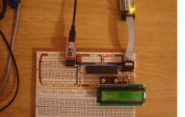
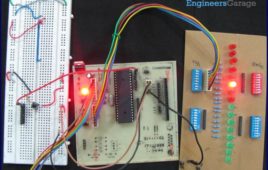
In the AVR microcontroller the flash memory is divided into two parts, namely Application Section and Boot Loader Section. A code can be programmed into either the Application Section or the Boot loader Section (BLS). The code programmed into the Application section runs normally and is used for common applications, whereas the code running in the BLS is provided with some special features. The code running in the BLS section can execute Self Programing Mode (SPM) instructions which are blocked for the code running in the Application section. Using SPM instructions the code from the BLS can rewrite the code in the application section or the code in the BLS itself. The BLS section is normally used for storing the Boot-loader code for the microcontroller. The Boot-Loader code can be used for initializing the peripherals in the microcontroller, initialize the devices connected to the microcontroller, select the application to load and execute from a storage medium, load the selected application to the application section, jump to the application section and execute the application.
Interfacing SD Card with AVR Microcontroller- (Part 38/46)
This project explains how to interface the SD card with an AVR microcontroller. In this project an ATMEGA16 microcontroller is used. The microcontroller runs on 5V power supply with a built in crystal frequency of 8 MHz. A 2GB SDSC card from Transcend is used in this particular project, but the code will work with most of the SD cards. The SD card is formatted with FAT32. The ultimate aim of this project is to read a file from the FAT32 file system of the SD card.The SD card has been formatted as FAT32 before interfacing. The generalized code for the FAT32 is written to interface the SD card. Explanations of the FAT32 file system and how to access files from these file system is explained in this project.This project explains the SD card interfacing with an AVR microcontroller and circuit working in detail. Read more to find out how this project works and do it yourself!!!
How to interface GPS with AVR microcontroller (ATmega16)- (Part 43/46)
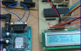
GPS modem is a device which receives signals from satellite and provides information about latitude, longitude, altitude, time etc. The GPS navigator ismore famous in mobiles to track the road maps. The GPS modem has an antenna which receives the satellite signals and transfers them to the modem. The modem in turn converts the data into useful information and sends the output in serial RS232 logic level format. The information about latitude, longitude etc is sent continuously and accompanied by an identifier string.This article shows how to interface the GPS modem with ATmega16 and extract the location (latitude and longitude) from the GPGGA string and display it on LCD. The connection of GPS modem with AVR microcontroller (ATmega 16) is shown in the circuit diagram. The ground pin of max 232 and serial o/p of GPS modem is made common. Pin2 of MAX232 is connected to pin 3 of GPS modem and pin 3 of max 232 is connected to pin 2 of modem. This type of connection is called a serial cross cable.
How to configure Watchdog Timers of AVR Microcontroller (ATmega16)- (Part 15/46)

Some high end applications require multiple or critical calculations to be done by the microcontroller. This may lead to cases when the controller enters intowrong or infinite loops. As a result of this, the system either hangs up or gets crashed. The solution to overcome these situations is to automatically reset the system whenever such a situation arises.The Watchdog Timer is a hardware or software generated timer interrupt which reboots/resets the system in the situations mentioned above. The watchdog timers are also used in cases when you intentionally require resetting the system without any physical interference.The AVR microcontroller has an in-built watchdog timer. This article explains the working of watchdog timer in ATmega16. The Watchdog Timer is a special timer which can be enabled in any section of the code and when enabled it ensures that a certain number of instructions execute within a pre-defined time frame. This time frame or the time delay can be configured/set using the registers of the watchdog timer.
How to interface serial ADC0831 with AVR microcontroller (ATmega16)- (Part 27/46)
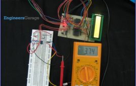
ADC is an electronics device that converts the analog signals to digital number proportional to the magnitude of voltage. The ADClike ADC0804, ADC0809 etc., give 8-bit digital output. The controller device needs eight pins to receive the 8-bit data (For more details about ADC refer to Using Inbuilt ADC of AVR). Some applications need higher resolution ADCs, (10 or higher bits digital data output) for data accuracy. Using parallel ADCs is one option for such applications. However using parallel ADC will increase the size of the hardware as a 10-bit parallel ADC will have 10 output lines. Also you might have to use controller with higher number of pins. The other option is to use serial ADC, which needs smaller number of pins. Since the data is transmitted serially, the data transfer rate of the serial ADC is low as compared to parallel ADC. They can serve as a very good alternative in applications where speed of data transfer in not a critical point. This article explores interfacing of serial ADC0831 with ATmega16.
How to take input from a particular pin of ATmega16- (Part 5/46)
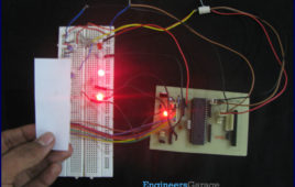
For understanding the human needs a system must be able to take input from user. The devices which can be used to take input for a system are keypad, touch [[wysiwyg_imageupload::]]screen, etc. In the article LED blinking, the microcontroller drives the LED or in embedded language the microcontroller was set to give o/p, this article gives brief information of getting an input from user at a particular pin of microcontroller. In order to take input from an external source on any of the pins of the AVR microcontroller, the pins need to be configured as input pin. This configuration informs the controller that the corresponding pins are used to take input. Read more to find out how the circuit is constructed and how the IC can be programmed to work in the desired manner.
How to use I2C / TWI (Two Wire Interface) in AVR ATmega32- (Part 36/46)
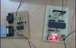
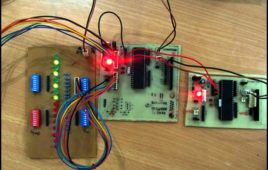
This article explores the TWI interfacing between two ATmega32 controllers. Readers are advised to go through TWI Communication and TWI registers[[wysiwyg_imageupload::]]of ATmega32 before going further. Generally modes 1 & 3 and modes 2 & 4 are used together. This article explains the use of these four modes by an experiment.To establish the communication between two ATmega32 using TWI interface. First the Master starts by sending data then the slave transmits complement of the received data to the master. When the Master receives the complemented data, it shifts the original data to left. This process of transmitting and receiving continues. As the data value reaches 0x80 the whole process is repeated. At the starting, value of the original data is 0x01. The received value is displayed on PORTB at both the ends.
How to interface Servo Motor with AVR Microcontroller (ATmega16)- (Part 21/46)
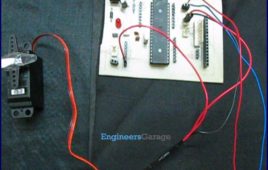
Servo motors find huge applications in industries in the field of automation, control & robotics. The servo motors are well known for their precise control and work [[wysiwyg_imageupload::]]on the principle of servo mechanism. The servo motors can be made to run at precise angle using PWM. The PWM (pulse width modulation) is the basic working principle behind a servo motor (For more details about PWM refer Phase correct PWM mode). This article explores the interfacing of servo motor with ATmega16. Also to know more about servo mechanism see Interfacing Servo Motor with 8051. There are different types of servos available in the market. This article bounds its scope to interfacing a commonly available servo, widely used by hobbyist with ATmega16. Such a servo consists of three wires positive supply, ground and a control signal. Unlike other motors, Servo motors don’t require any driver. When a PWM signal is applied to its control pin the, the shaft rotates to a specific angle depending on the duty cycle of the pulse.
How to interface keypad with AVR microcontroller (ATmega16)- (Part 11/46)
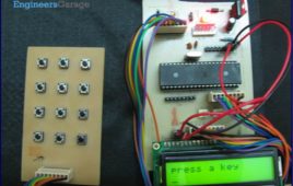
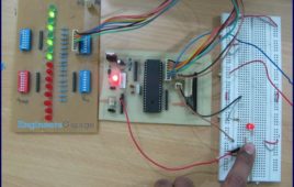
Keypad is most widely used input device to provide input from the outside world to the microcontroller. The keypad makes an application more users interactive. [[wysiwyg_imageupload::]]The concept of interfacing a keypad with the ATmega16 is similar to interfacing it with any other microcontroller. The article of Interfacing keypad with 8051 can be referred for detailed description of the methodology used here. This article explains the interfacing of a 4×3 keypad with AVR microcontroller(ATmega16) and displaying the output on a LCD. The algorithm and detailed explanation for keypad interfacing is given in above mentioned article. The brief steps to interface the keypad with AVR are written below:1. Configure the row pins or column pins.2. Make all output pins to low and input pins to high.3. Keep monitoring the port value, where the key pad is connected.
How to interface LED with AVR Microcontroller (ATmega16)- (Part 4/46)
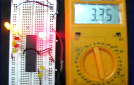
ATmega16 has 32 I/O pins to communicate with external devices. Before interfacing with external devices, these pins must be cofigured as input or output pin. [[wysiwyg_imageupload::]]This article demonstrates the basic I/O operation of ATmega 16 using LEDs. All the four ports can be configured to read an input from some external device or to give output to any external device as per the application. For e.g., a switch is connected to a particular pin, that pin should be configured as input to read the values from the switch (external Device in this case) and if you are connecting a LED to any pin of the port then that particular pin should be configured as output to transmit the signal to the LED (external device in this case). A single port can be configured such that some of the pins of the same port are input and some are output. Read on more to understand how LED interfacing is done with the help of an AVR.
How to use External (Hardware) Interrupts of AVR Microcontroller (ATmega16)- (Part 22/46)
When an interrupt occurs, the normal flow of instructions is suspended by the microcontroller and the code corresponding to the interrupt, which has occurred, is executed. Once the code corresponding to the interrupt is executed completely the execution again begins from the same instruction where it was stopped. Following is what happens when an interrupt…
Serial communication (USART) with different frame size using AVR microcontroller- (Part 14/46)
The previous article explains serial communication using 8-bit data transfer. AVR microcontroller also supports serial data transfer with frame size of 5, 6, 7 and 9 [[wysiwyg_imageupload::]]data bits. The size of data frame can be adjusted according to application. For example, consider a system that needs to transmit only ASCII codes as data. In this case data frame size of 7-bits is sufficient because data length of ASCII code is equal to 7-bit. This will makes system more efficient by saving time of one clock period in each data frame transmission. This article explains serial transfer of data with different frame size. A test program is written for 6-bit data communication between Microcontroller and PC. In this experiment the input is taken from the user through a keyboard. The corresponding data is sent to microcontroller via PC’s COM port. The microcontroller receives data and returns it again to PC’s COM port. The HyperTerminal is used to configure COM port to make it compatible for this experiment.
Waveform Generation using AVR Microcontroller (Atmega16) Timers- (Part 16/46)
At times we come across applications or situations wherein we need to generate square waves with the microcontroller. The square wave can be generated by [[wysiwyg_imageupload::]]programming a pin which toggles between 0 and 1 with a certain time delay. Alternatively, the inbuilt feature of AVR timers can be used in square wave generation. The advantage of using AVR timers in wave form generation is that the output pin toggles automatically when the timer condition are fulfilled. This article focuses on usage of AVR timer for simple square wave generation. It is better to use CTC mode instead of Normal mode because in CTC mode, frequency can be easily adjusted. ?When the Timer is triggered, register TCNTn counts the value constantly as timer started. Each timer has an OCRn (Output Compare Register), which is continuously compared with TCNTn register. In CTC mode whenever match occurs, OCFn (Output Compare Flag) will set to 1. If continuous wave form generation is required, OCFn must be reset again. Alternatively, if OCIEn (Output Compare interrupt) and Global interrupt flags in SREG are set, OCFn will reset automatically after interrupt execution.
Phase Correct PWM (Pulse Width Modulation) Mode of AVR microcontroller Timer- (Part 17/46)
Pulse Width Modulation is well known technique for controlling power electronics devices like SCR, IGBT etc. PWM is also used in motor speed controlling.[[wysiwyg_imageupload::]] Square wave generation by using AVR timers is explained in previous article. The AVR timers have feature of PWM wave generation as well .This article describes PWM generation capability of AVR timers. There are four in-built PWM channels in ATmega16. The PWM outputs are received on pins OC0, OC1A, OC1B and OC2. Readers can refer the previous article which gives explanation of these pins. The Phase correct PWM mode can be selected by assigning bits WGM0[1:0]=01. This mode is based on dual slope operation. In dual slope operation, TCNTn counts from bottom value to maximum value and maximum value to bottom value. The OCRn register compares the value with the TCNTn register constantly during up-counting and down-counting. On compare match PWM output pin (OCn) behaves according to inverting or non-inverting mode which can be selected by programming of COMn [1:0] bits.
How to use fast PWM (Pulse Width Modulation) Mode of AVR microcontroller Timer- (Part 18/46)
This article is in continuation of PWM generation using AVR timer. In the previous article, PWM generation using Phase correct PWM mode is described. [[wysiwyg_imageupload::]]However, there are some applications like DAC, power regulation and rectification etc. which require high frequency PWM wave. The PWM generation using Fast PWM mode is suitable for such applications. This article focuses on Fast PWM mode of AVR Timer. The Fast PWM mode is based on single-slope operation. In single slope operation, the register TCNTn counts from bottom value to maximum value and its value resets to zero. The counting starts again from bottom. The register OCRn compares the value with the TCNTn register constantly. If the timer is configured in non-inverting mode, PWM output pin (OCn) goes low when the value of the above two registers matches. The OCn pin becomes high when the TCNTn register reaches at bottom value. In inverting mode OCn pin behaves opposite to non-inverting mode. For timer 0 fast PWM mode, following table shows the functionality of COM 0[1:0] bits.
SPI (serial peripheral interface) using AVR microcontroller (ATmega16)- (Part 37/46)
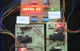
There are different protocols for serial communication between two deceives like, USART, SPI, I2C etc. Before selecting any communication protocol, data transfer [[wysiwyg_imageupload::]]rate is an important parameter. SPI transfers data at high speed data. AVR microcontroller contains on chip SPI interface. This article will explore the hardware configuration and programming of SPI. Serial Peripheral Interface is a synchronous, full-duplex protocol. SPI is also known as “3-wire interface” protocol because it needs 3 communication lines named MISO, MOSI and SCK. SPI protocol needs two devices for communication. One of them is considered as a MASTER and another one as a SLAVE.AVR microcontrollers contain both MASTER and SLAVE interface on single chip. Thus, a microcontroller can work as both master and slave device. The SPI is synchronous data transfer protocol, so clock pulse is needed to synchronize both master and slave device. The clock pulse is generated from master side. The SCK pin of master provides clock pulse to slave device.
How to interface LCD in 4 bit mode with AVR microcontroller- (Part 10/46)
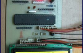
This article explains interfacing of LCD with ATmega16 using 4-bit mode. In this mode only four pins are used for sending data and command instructions. This [[wysiwyg_imageupload::]]mode has the advantage over the 8-bit mode as it uses less number of pins. The remaining pins of the controller are available for normal use. The Data or command is sent in nibble form (1 nibble= 4 bit) in the 4-bit mode. The higher nibble is sent first followed by the lower nibble. The function of RS, RW and EN pins remains similar to 8-bit mode. The LCD can be configured in 4-bit mode by sending appropriate instruction which is called “Function set” to it. The Function set is hexadecimal instruction for LCD MPU unit, which selects working modes of LCD. Continue reading to find out LCD can be interfaced with simple programming and circuitry.
How to disable JTAG of AVR microcontroller- (Part 24/46)
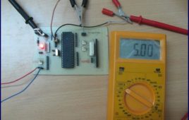
JTAG stands for “Joint Test Action Group” which was standardized as the IEEE 1149.1 Standard Test Access Port and Boundary-Scan Architecture in 1990. JTAG [[wysiwyg_imageupload::]]is generally used in IC debugging and device programming. Atmega16 consists of one JTAG port which shares four pins with PORTC. Until JTAG port is not disabled, these pins can’t be used as normal I/O pins. This article explores the methods for JTAG disabling. JTAG interface shares PC2, PC3, PC4 and PC5 of ATmega16. To use these four pins for general I/O operations, JTAG must be disabled. There are two methods for disabling JTAG: 1. By programming2. Using AvrdudeThere is a register in atmega16 MCUCSR (MCU control and status register). It consists of JTD (JTAG disable) bit as 7th bit of register. JTAG can be disabled by writing 1 to this bit.JTAG can be permanently disabled by configuring two fuse bits, OCDEN and JTAGEN (must be disabled). This is done by using Avrdude software.
How to use inbuilt analog comparator of AVR microcontroller- (Part 29/46)
Analog comparator is a device which compares two input voltages and generates output accordingly. The article on IR sensor explains the use of comparator in [[wysiwyg_imageupload::]]sensor designing. Comparators form an integral part of circuit designing in majority of the applications. AVR microcontrollers have in-built analog comparator. Using the in-built analog comparator of AVR, the controller can be used to compare the signal and process the signal as well. This reduces the external comparator components on our circuits. In this article proximity sensor is designed using in-built analog comparator of ATmega16. The analog comparator needs two inputs positive and negative. The positive input is given on AIN0 (PB2) pin of controller. In ATmega16 nine pins are available to connect negative input of comparator. This means microcontroller can compare maximum of nine analog signals with one positive input voltage. Although, signals are not compared simultaneously but the time difference between two consecutive comparisons is of the order of microseconds which is quite low to identify. The negative input of comparator is applied on pin AIN1 (PB3).