Engineers Garage

  • Electronic Projects & Tutorials
    • Electronic Projects
      • Arduino Projects
      • AVR
      • Raspberry pi
      • ESP8266
      • BeagleBone
      • 8051 Microcontroller
      • ARM
      • PIC Microcontroller
      • STM32
    • Tutorials
      • Audio Electronics
      • Battery Management
      • Brainwave
      • Electric Vehicles
      • EMI/EMC/RFI
      • Hardware Filters
      • IoT tutorials
      • Power Tutorials
      • Python
      • Sensors
      • USB
      • VHDL
    • Circuit Design
    • Project Videos
    • Components
  • Articles
    • Tech Articles
    • Insight
    • Invention Stories
    • How to
    • What Is
  • News
    • Electronic Product News
    • Business News
    • Company/Start-up News
    • DIY Reviews
    • Guest Post
  • Forums
    • EDABoard.com
    • Electro-Tech-Online
    • EG Forum Archive
  • DigiKey Store
    • Cables, Wires
    • Connectors, Interconnect
    • Discrete
    • Electromechanical
    • Embedded Computers
    • Enclosures, Hardware, Office
    • Integrated Circuits (ICs)
    • Isolators
    • LED/Optoelectronics
    • Passive
    • Power, Circuit Protection
    • Programmers
    • RF, Wireless
    • Semiconductors
    • Sensors, Transducers
    • Test Products
    • Tools
  • Learn
    • eBooks/Tech Tips
    • Design Guides
    • Learning Center
    • Tech Toolboxes
    • Webinars & Digital Events
  • Resources
    • Digital Issues
    • EE Training Days
    • LEAP Awards
    • Podcasts
    • Webinars / Digital Events
    • White Papers
    • Engineering Diversity & Inclusion
    • DesignFast
  • Guest Post Guidelines
  • Advertise
  • Subscribe

How to design a lab power supply at home

By Ashutosh Bhatt September 22, 2024

The voltage requirements for different circuits vary much like microcontroller-based circuits require 5 V, motor controller or relay driver circuit requires 12 V, and other digital circuits require 3.3 V. 

If a circuit fails to receive its rated voltage and current, it will not work properly. So, it often makes sense to use a variable power supply.

In this circuit, we’ll design a lab power supply to provide voltage and current requirements for testing various circuits and devices.

Here are the lab’s essentials: 

1. Must provide a regulated output
2. Must supply the required current to the circuit under test
3. Its output voltage must be adjustable to the required voltage
4. It should have a digital display for voltage and current 

Several lab power supplies are available to meet all the above requirements, but they’re typically quite costly. 

Other problems include:

  • BIG in size
  • Bulky and heavy
  • Not portable
  • Occupies a lot of space

Unfortunately, most electronics hobbyists, teachers, or students cannot afford such power supplies in their home or laboratory. But we have a solution.

Let’s build a compact, portable lab power supply with all of the essential features.

Specifications

1. Regulated output voltage with voltage regulator chips LM317 and LM7805
2. Adjustable output voltage: 1.25  to 23 V
3. Maximum output current 2 A
4. Linear and precise output voltage
5. Digital display for voltage and current
6. Dual supply (1) variable supply: 1.2 – 23V (2) fixed supply: 5 V
7. Compact and lightweight design
8. Portable and occupies little space
9. Total cost around 425 /- Rs

This power supply uses the popular voltage regulator IC LM317. It has a simple circuit and is easy to build. It also has a digital VA meter that displays the output voltage and current. Let’s get started.

Circuit diagram

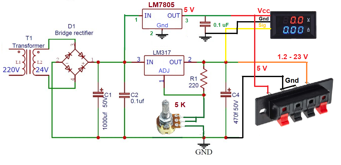
Circuit diagram of the lab power supply using IC LM317 and LM7805.

As shown in the above diagram, the circuit uses voltage regulator chips LM317 and LM7805, as well as a few additional components such as a bridge rectifier, capacitors, resistors, and potentiometer. 

Circuit connections

  • The primary of transformer T1 is connects with 230 V of AC input
  • Its secondary connects with the AC input terminals of the bridge rectifier
  • The bridge rectifier’s output is given as input to both ICs LM317 and LM7805
  • One 5 K pot connects to the adjustment input of the LM317 IC
  • LM7805’s 5 V output connects with the output socket and to the VCC supply of the digital VA meter
  • The variable output of LM317 also connects to the output socket and provides a signal input of digital VA meter

Circuit operation

  • T1 is 12-0-12 @ 2A transformer, which steps down the 230 V AC input to 24 V AC, providing it as input to the bridge rectifier D1
  • The bridge rectifier gives rectified output that’s filtered to the pulsating DC via the capacitors C1 and C2 4. This output is provided as an input to both voltage regulator ICs
  • The LM7805 generates regulated 5 V of output, which is used as supply voltage to the digital VA meter
  • The 5 V output is also taken out from external connector so that it can be used for the external circuit
  • The LM317 generates a variable output voltage from 1.2 to 23 V as the potentiometer varies

The equation for output voltage of LM317 is:

Vout = 1.25 (1 + R2/R1)

Here… R2 = 5 K pot and R1 = 220 ohm
So, when R2 = 0

Vout = 1.25 (1 + 0) = 1.25 V

And when R2 = 5000

Vout = 1.25 (1 + 5000/220) = 30 V*

*Note: the maximum output will be 23 – 24 V because the AC input is 24 V

This output is given as signal input (the yellow wire) to the digital VA meter. The varying output voltage is displayed on meter. Also, the variable output voltage is connected to external connector.

Circuit assembly and housing
The complete circuit and a transformer are housed in a specially designed MDF box as shown below.

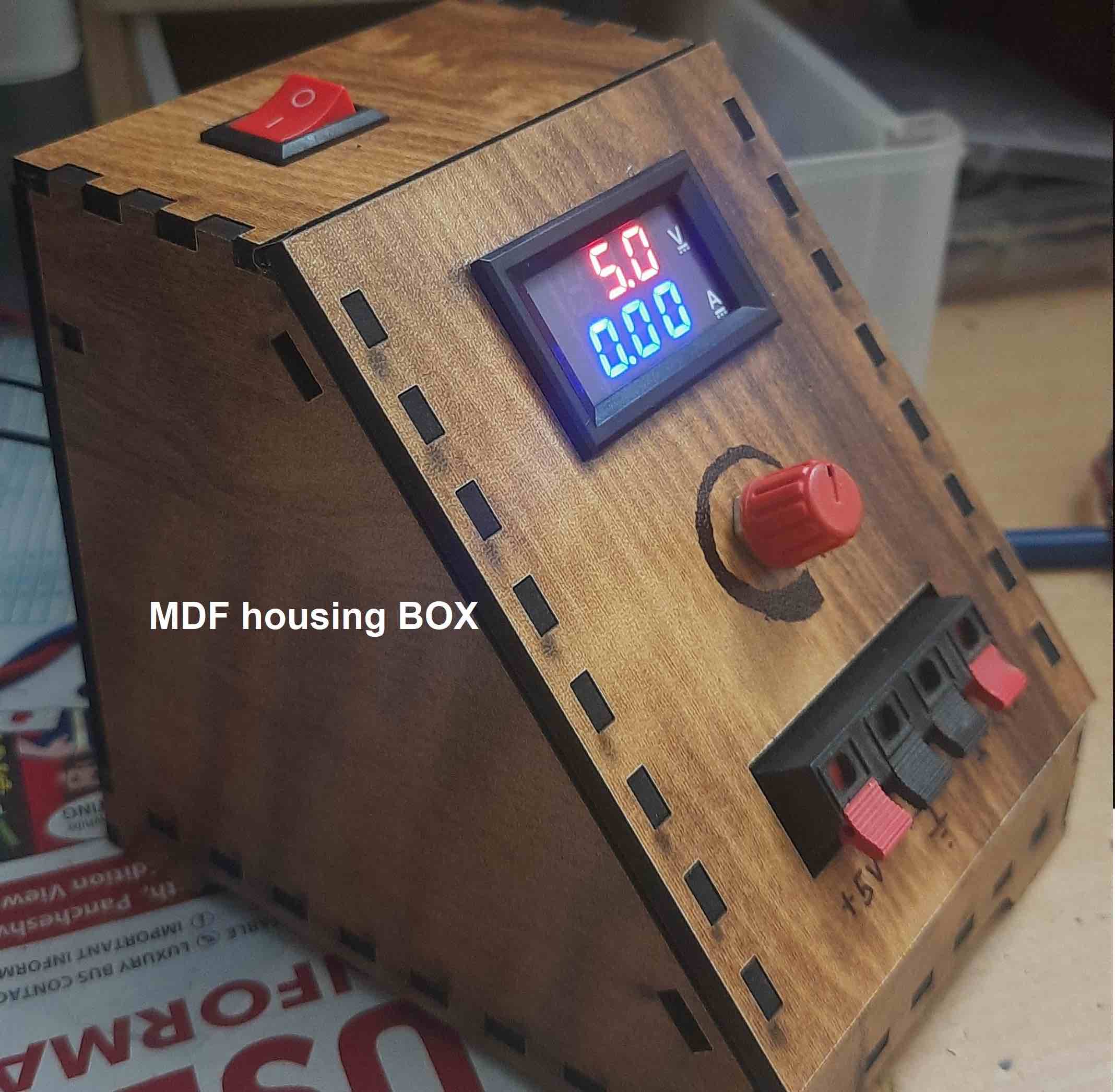
Prototype of the complete circuit and transformer designed in the MDF box.

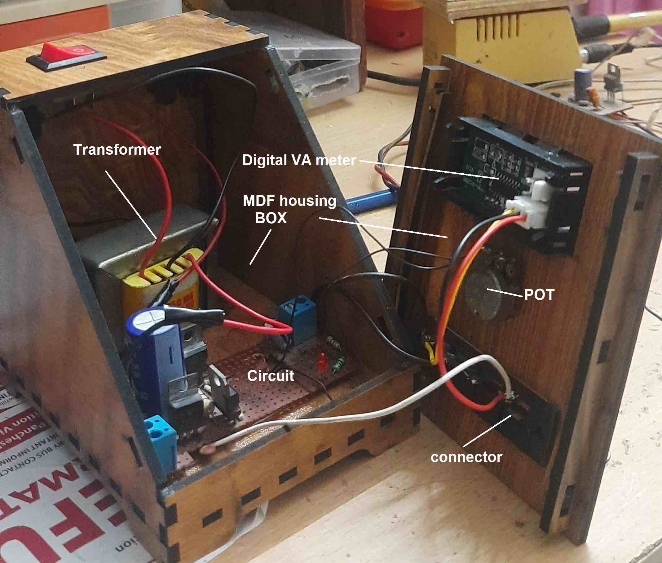
The open MDF box with the different components.

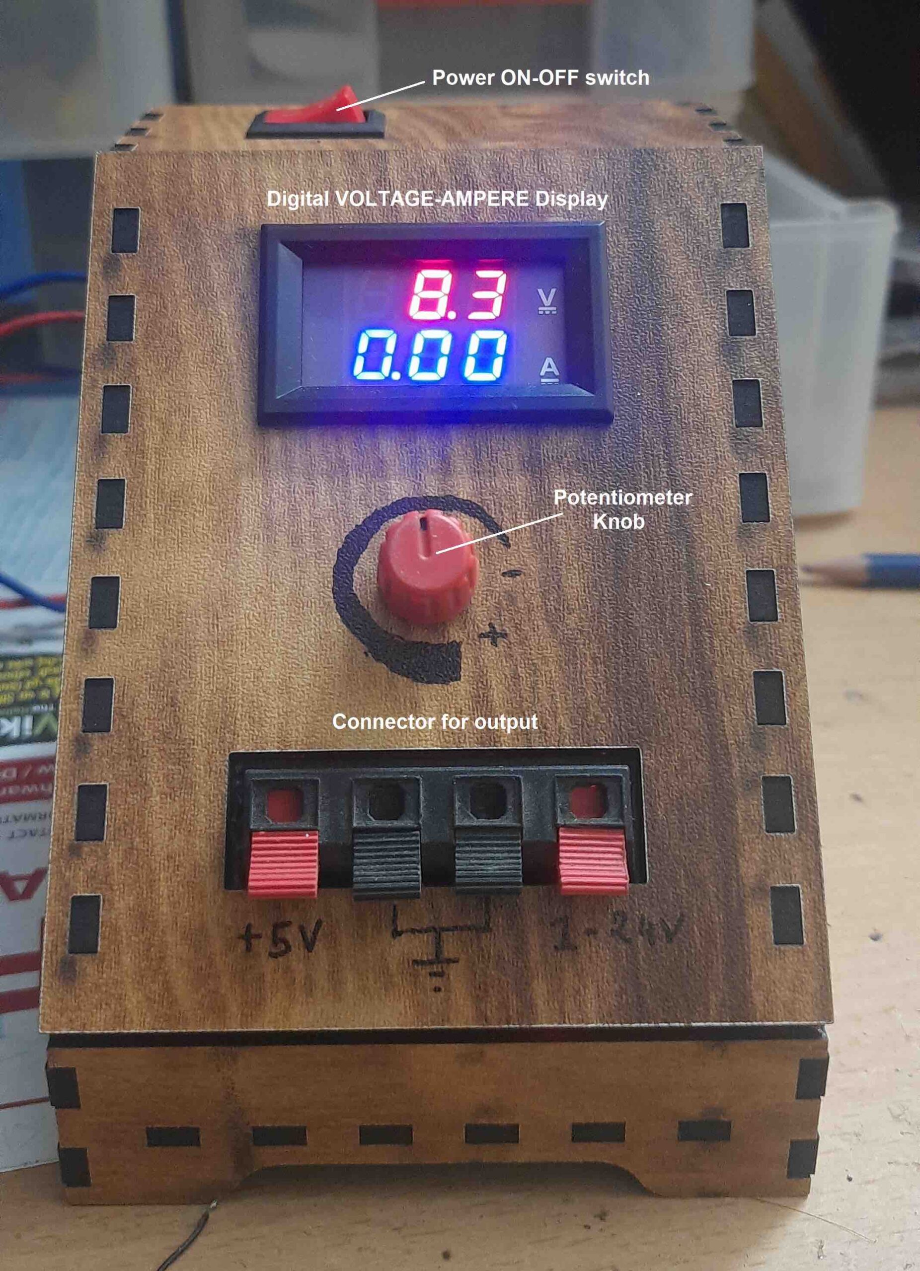
The digital display, potentiometer, and output connector are fixed in the front panel as shown in the below image. There’s also a power on-off switch on top.

The MDF box with the digital voltage ampere display, potentiometer knob, and switch.

Now, let’s break down the costs. Here is the BOM (bill of materials)…

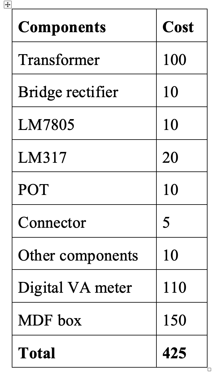
This simple lab power supply can be built at home for less than 500/- R. Now, it’s your turn!

Here is a YouTube video for a closer look at how to build this lab power supply at home:

You may also like:

  • beginners guide
    Basic Electronics 01 – Beginners guide to setting up an…

  • Component selection for low power embedded systems
  • VHDL
    VHDL Tutorial 1: Introduction to VHDL

  • What is an SoC?

  • What is electronic design automation?

  • What is an embedded system?

  • What is an Integrated Circuit? Specifications to tapeout

Filed Under: Circuit Design
Tagged With: lab, power, powersupply, tutorial
 

Next Article

← Previous Article
Next Article →

Questions related to this article?
👉Ask and discuss on EDAboard.com and Electro-Tech-Online.com forums.


Tell Us What You Think!! Cancel reply

You must be logged in to post a comment.

EE TECH TOOLBOX

“ee
Tech Toolbox: Internet of Things
Explore practical strategies for minimizing attack surfaces, managing memory efficiently, and securing firmware. Download now to ensure your IoT implementations remain secure, efficient, and future-ready.

EE Learning Center

EE Learning Center
“engineers
EXPAND YOUR KNOWLEDGE AND STAY CONNECTED
Get the latest info on technologies, tools and strategies for EE professionals.

HAVE A QUESTION?

Have a technical question about an article or other engineering questions? Check out our engineering forums EDABoard.com and Electro-Tech-Online.com where you can get those questions asked and answered by your peers!


RSS EDABOARD.com Discussions

  • Reducing "shoot-through" in offline Full Bridge SMPS?
  • High Side current sensing
  • How to simulate power electronics converter in PSpice?
  • Voltage mode pushpull is a nonsense SMPS?
  • Layout IRN reduction in Comparator

RSS Electro-Tech-Online.com Discussions

  • Back to the old BASIC days
  • Parts required for a personal project
  • PIC KIT 3 not able to program dsPIC
  • Failure of polypropylene motor-run capacitors
  • Siemens large industrial PLC parts

Featured – RPi Python Programming (27 Part)

  • RPi Python Programming 21: The SIM900A AT commands
  • RPi Python Programming 22: Calls & SMS using a SIM900A GSM-GPRS modem
  • RPi Python Programming 23: Interfacing a NEO-6MV2 GPS module with Raspberry Pi
  • RPi Python Programming 24: I2C explained
  • RPi Python Programming 25 – Synchronous serial communication in Raspberry Pi using I2C protocol
  • RPi Python Programming 26 – Interfacing ADXL345 accelerometer sensor with Raspberry Pi

Recent Articles

  • What is AWS IoT Core and when should you use it?
  • AC-DC power supply extends voltage range to 800 V DC
  • Infineon’s inductive sensor integrates coil system driver, signal conditioning circuits and DSP
  • Arm Cortex-M23 MCU delivers 87.5 µA/MHz active mode
  • STMicroelectronics releases automotive amplifiers with in-play open-load detection

EE ENGINEERING TRAINING DAYS

engineering

Submit a Guest Post

submit a guest post
Engineers Garage
  • Analog IC TIps
  • Connector Tips
  • Battery Power Tips
  • DesignFast
  • EDABoard Forums
  • EE World Online
  • Electro-Tech-Online Forums
  • EV Engineering
  • Microcontroller Tips
  • Power Electronic Tips
  • Sensor Tips
  • Test and Measurement Tips
  • 5G Technology World
  • Subscribe to our newsletter
  • About Us
  • Contact Us
  • Advertise

Copyright © 2025 WTWH Media LLC. All Rights Reserved. The material on this site may not be reproduced, distributed, transmitted, cached or otherwise used, except with the prior written permission of WTWH Media
Privacy Policy

Search Engineers Garage

  • Electronic Projects & Tutorials
    • Electronic Projects
      • Arduino Projects
      • AVR
      • Raspberry pi
      • ESP8266
      • BeagleBone
      • 8051 Microcontroller
      • ARM
      • PIC Microcontroller
      • STM32
    • Tutorials
      • Audio Electronics
      • Battery Management
      • Brainwave
      • Electric Vehicles
      • EMI/EMC/RFI
      • Hardware Filters
      • IoT tutorials
      • Power Tutorials
      • Python
      • Sensors
      • USB
      • VHDL
    • Circuit Design
    • Project Videos
    • Components
  • Articles
    • Tech Articles
    • Insight
    • Invention Stories
    • How to
    • What Is
  • News
    • Electronic Product News
    • Business News
    • Company/Start-up News
    • DIY Reviews
    • Guest Post
  • Forums
    • EDABoard.com
    • Electro-Tech-Online
    • EG Forum Archive
  • DigiKey Store
    • Cables, Wires
    • Connectors, Interconnect
    • Discrete
    • Electromechanical
    • Embedded Computers
    • Enclosures, Hardware, Office
    • Integrated Circuits (ICs)
    • Isolators
    • LED/Optoelectronics
    • Passive
    • Power, Circuit Protection
    • Programmers
    • RF, Wireless
    • Semiconductors
    • Sensors, Transducers
    • Test Products
    • Tools
  • Learn
    • eBooks/Tech Tips
    • Design Guides
    • Learning Center
    • Tech Toolboxes
    • Webinars & Digital Events
  • Resources
    • Digital Issues
    • EE Training Days
    • LEAP Awards
    • Podcasts
    • Webinars / Digital Events
    • White Papers
    • Engineering Diversity & Inclusion
    • DesignFast
  • Guest Post Guidelines
  • Advertise
  • Subscribe