The ESP32-CAM is a widely used development board for embedded vision applications. It combines the ESP32 microcontroller with an OV2620 camera module, and the ESP32 itself comes with built-in Wi-Fi and Bluetooth capabilities. Previously, we created a video streaming server using the ESP32-CAM to troubleshoot potential operational issues with the module.
In this project, we’ll program the ESP32-CAM to capture still images and store them on a MicroSD card. The module will capture live images whenever the reset button is pressed, offering a simple yet effective solution for capturing images.
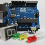
Components
- ESP32-CAM x1
- Arduino UNO or MEGA x1
- USB cable (to connect Arduino with your computer)
- Jumper wires
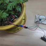
Circuit connections
In this project, we use Arduino to upload a sketch to the ESP32-CAM. However, Arduino UNO or MEGA also work.
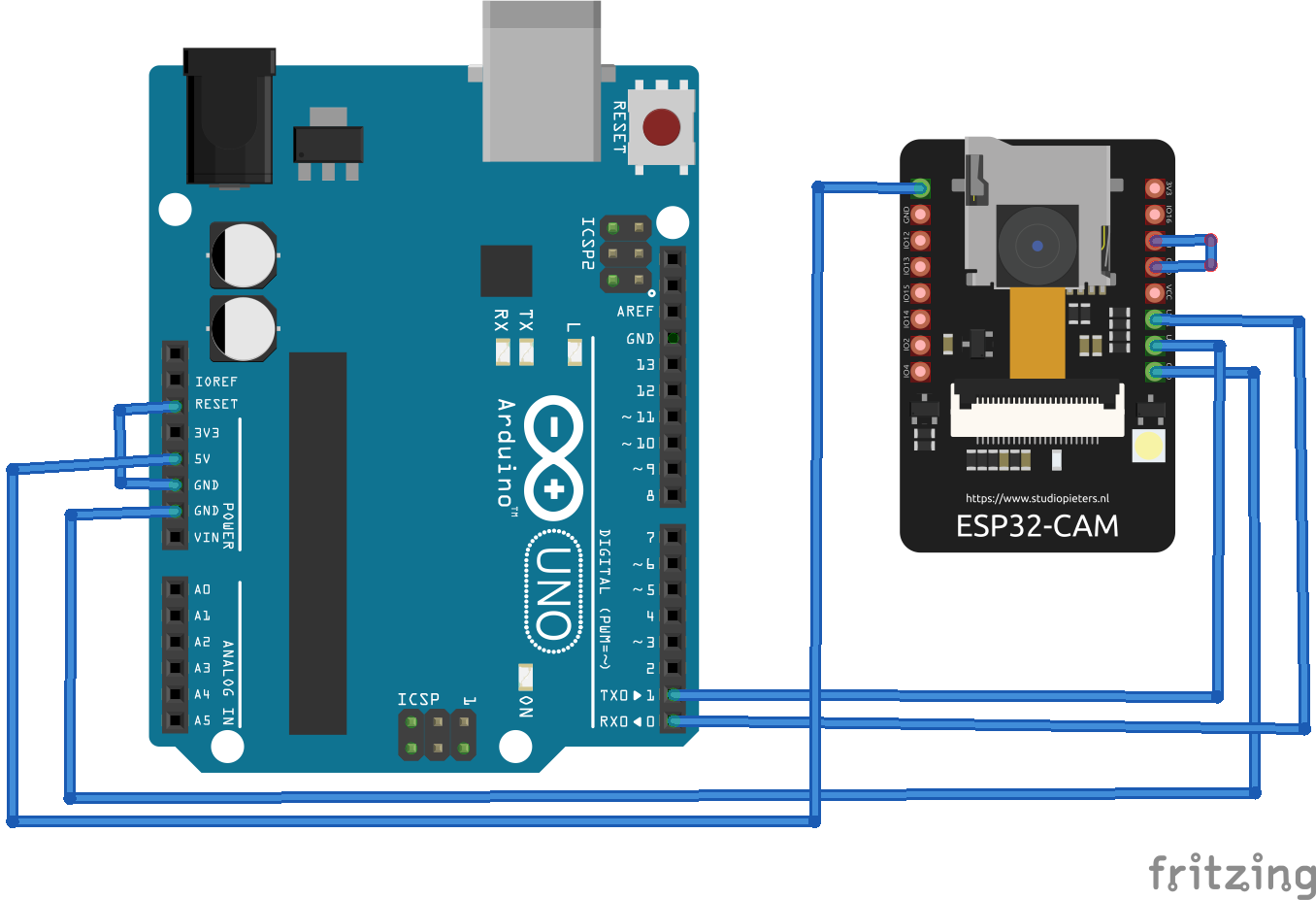
Begin by connecting ESP32-CAM’s GPIO1 (U0_TXD) and GPIO3 (U0_RXD) pins to Arduino’s TX and RX pins, respectively. Next, connect ESP32-CAM’s 5V and ground pins to Arduino’s 5V and GND pins. Also, connect Arduino’s RESET pin to its ground pin.
While uploading the sketch, ensure that ESP32-CAM’s GPIO0 pin is connected to its ground pin. After successfully uploading the sketch, be sure to remove the connection between ESP32-CAM’s GPIO0 and ground.
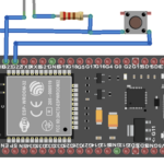
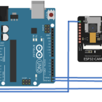
Below is the circuit diagram illustrating the connections between Arduino and the ESP32-CAM for uploading the sketch.
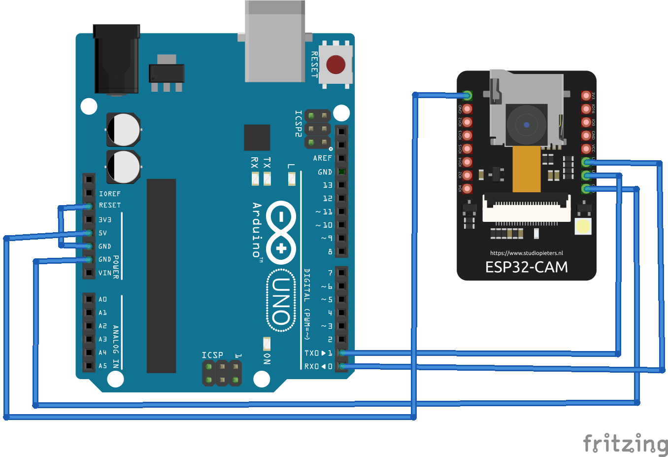
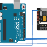
Next, is a circuit diagram that demonstrates the connections between Arduino and the ESP32-CAM. It relates to the camera after the sketch uploaded. Note that the connection between ESP32-CAM’d GPIO0 and ground pins is removed.
The sketch
Uploading the sketch
Complete the circuit connections as instructed to properly upload the code. Remember to connect ESP32-CAM’s GPIO0 with its ground pin to do so.
Now, connect Arduino with a computer using a USB cable. Select the “ESP32 Wrover Module” as the board to use, and set the following parameters under “Tools.”
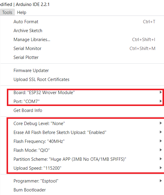
Compile and upload the sketch by clicking on Arduino IDE’s “Upload” button. After the sketch is uploaded, remove the connection between ESP32-CAM’s GPIO0 and ground pins via Arduino.
Format a MicroSD card to the “FAT32 file system” using a suitable SD card formatter. Then, insert the card in ESP32-CAM’s MicroSD card slot. The development board should be ready to capture still images.
How it works
In the firmware code that’s uploaded to the ESP32-CAM, the board is programmed to initialize the camera module and take a picture. This captured image is instantly stored in the attached MicroSD card. The complete code runs in the setup() function and only functions when the module’s reset button is pressed. After capturing a new image, the module goes in idle mode as the loop() function in the firmware has no code.
The code
The sketch begins with importing the libraries required for operating the module. like esp_camera.h,Arduino.h etc. The libraries FS.h and SD_MMC.h are required for working with the SD card. The libraries soc/soc.h and soc/rtc_cntl_reg.h are required for handling the brownout problem. The library driver/rtc_io.h is required for handling RTC input and outputs.
The EEPROM.h is save data in the flash memory. The ESP32-CAM has an EEPROM of size 4 kilobytes available. Out of that storage, one byte is defined as a constant to denote the maximum number of images to be taken. One byte allows up to 256 pictures.
The sketch begins by importing the necessary libraries for operating the ESP32-CAM module, such as esp_camera.h and Arduino.h. Additional libraries, including FS.h and SD_MMC.h, are required to work with the SD card. The soc/soc.h and soc/rtc_cntl_reg.h libraries address the brownout detection problem. The driver/rtc_io.h library manages the RTC input and output functionality, and EEPROM.h is included to enable data storage in the flash memory.
The ESP32-CAM features a four-kilobyte EEPROM, with one byte designated as a constant to define the maximum number of images that can be stored — allowing up to 256 pictures.
Constants for the pin configuration of the ESP32-CAM module are declared, followed by the initialization of a variable to store the image count, which is set to “0.”
In the setup function, the camera module is configured by defining its various settings. If PSRAM is available, specific settings are defined. Otherwise, alternative settings are applied. Both the camera and the MicroSD card are initialized. The subsequent code in the sketch is responsible for capturing and saving images to the MicroSD card.
This code in the sketch captures an image:
fb = esp_camera_fb_get();
if(!fb) {
Serial.println(“Camera capture failed”);
return;
}
The EEPROM is initialized to retrieve the last stored picture number, and that number variable is incremented by “1” for the new capture. A storage path is defined on the MicroSD card, and the captured picture is saved at this specified location.
To maintain continuity, the updated picture number is written back to the EEPROM, allowing the system to track the total number of pictures taken.
To provide user feedback, the onboard LED flashes briefly to indicate that the picture has been successfully captured and stored. Once the process is complete, the ESP32-CAM module enters deep sleep mode to conserve power until the next activation.
All of the code is written in the setup() function, so it runs only once when the reset button is pressed. The development board remains in deep sleep state at all other times. The captured pictures can be viewed and retrieved from the MicroSD card module.
The results
The development board captures and stores pictures when the reset button is pressed, as shown in the demonstration video.
Video
The pictures are retrieved by inserting the MicroSD card in your computer.
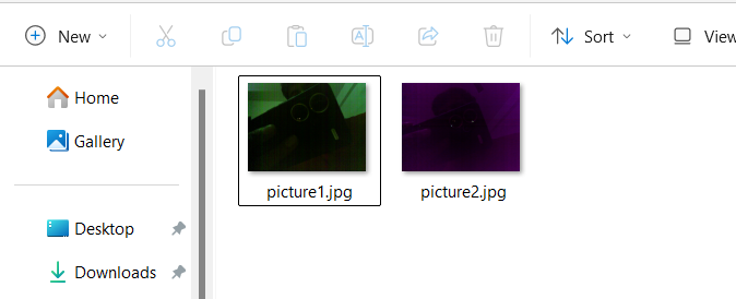
Some of the pictures we captured from the ESP32-CAM are as follows.
You may also like:


Filed Under: Electronic Projects, Video
Questions related to this article?
👉Ask and discuss on Electro-Tech-Online.com and EDAboard.com forums.
Tell Us What You Think!!
You must be logged in to post a comment.